Page 174 - EPR Catalog 2015
P. 174

Temperature monitoring relays
Connection diagrams, Resistance thermometer sensors

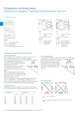
      Connection diagrams                                                    Y1 Y2     A1                          Y1 Y2     A1

         A 1 11 21                                                                  Memory             K1 15              Memory                                                                                                                                                                                                                                                      K1 15

2 T3 T2 T1                                                                   T1              1                18   1T1            1                                                                                                                                                                                                                                                          18
                                                                             T2              2                16   1T2                                                                                                                                                                                                                                                                       16
          T1 T2 T3 11 21                                                     T3                        K2 25                                                                                                                                                                                                                                                                          K2 25
                                                                                                                   1T3
             A1 A2 12 14 22 24                                                                                28                                                                                                                                                                                                                                                                             28
                                                                                                              26   2T1                                                                                                                                                                                                                                                                       26
          24 22                                                                                        K3 33       2T2 2                                                                                                                                                                                                                                                              K3 33
          14 12 A2
        CM-TCS                                                                                                34   2T3                                                                                                                                                                                                                                                                       34
        A1-A2 Control supply voltage                2CDC 252 025 F0010
        11-12/14 Output relay R1                                                                                                                                                                                                                                    1SVC 110 000 F0201Ready3T1
        21-22/24 Output relay R2                                                                                                                                                                                                                                                                                                                                    1SVC 110 000 F0202A23T2 Ready
        T1, T2, T3 Measuring input, connection PT100                                                               3T3

                                                                                                                             A2

                                                                             C512                                  C513

                                                                             A1-A2     Rated control suppy         A1-A2     Rated control suppy
                                                                                       voltage                               voltage
                                                                             15-16/18  Output contacts             15-16/18  Output contacts
                                                                             25-26/28                              25-26/28
                                                                             33-34     Sensor connection           33-34     Sensor connection 1
                                                                             T1-T3     Connection for              1T1-1T3   Sensor connection 2
                                                                             Y1-Y2     storage bridge              2T1-2T3   Sensor connection 3
                                                                                                                   3T1-3T3   Connection for
                                                                                                                   Y1-Y2     storage bridge

Connection of resistance thermometer sensors

2-wire measurement                                                               3-wire measurement

When using 2-wire temperature sensors the sensor resis-                          To minimize the influence of the wire resistance, a three-wire

tance and the wire resistance are added together.                                connection is usually used. By means of the additional wire

The resulting systematic errors must be taken into account                       two measuring circuits are created.                                                                                                                                                                                                                                                                  PT100

when adjusting the tripping device.                                PT100         One of these two circuits is used

A jumper must be connected between                                               for reference. This way, the tripping

the terminals T2 and T3.                                                         device can calculate and take into

The following table can be used for                                T1 T2 T3      account the wire resistance auto-                   T1 T2 T3
PT100 sensors to determine the
                                                                                 matically.
temperature errors caused by the line

length.

When using resistance sensors with

two-wire connection a bridge must be

inserted between terminals T2 and T3.

Error caused by the line                                                         Electrical isolation                   11 12 14
The error resulting from the line resistance amounts to ap-
prox. 2.5 Kelvin/Ohm. If the resistance of the line is not                                      11 12 14
known and it is not possible to measure it, the error caused
by the line can be estimated using the following table.

Temperature error                                                                   T1 21                          T1 21
(depending on the line length and conductor cross section                           T2 22                          T2 22
for PT100 sensors at an ambient temperature of 20 °C, in K)                         T3 24                          T3 24

                                                                                                24 V AC/DC                  24-240 V AC/DC
                                                                                                   A1 A2                          A1 A2
 Line length in m                                   Wire size mm2                                                 2CDC 252 019 F0010
                                                                                                                                                                                              2CDC 252 020 F0010
0
10                    0.50                          0.75 1             1.5
25
50                 0.0                              0.0   0.0      0.0                       Electrical isolation
75                 1.8                              1.2   0.9      0.6
100                4.5                              3.0   2.3      1.5                       Protective searation acc. to IEC/EN 61140; EN 50178
200                9.0                              6.0   4.5      3.0
500                13.6                             9.0   6.8      4.5
                   18.1                             12.1  9.0      6.0
                   36.3                             24.2  18.1     12.1
                   91.6                             60.8  45.5     30.2

2/107 ABB | Catalog Electronic Products and Relays 2015 | 2CDC 110 004 C0210
   169   170   171   172   173   174   175   176   177   178   179