
Page 260 - EPR Catalog 2015
P. 260
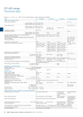
CP-ASI range
Technical data
Data at Ta = 25 °C, Uin = 230 V AC and rated values, unless otherwise indicated
Type CP-ASI/2.8 CP-ASI/4.0 CP-ASI/8.0 CP-ASI/4.0 DC/DC
Input circuit - Supply circuit L, N
Rated input voltage Uin - 24 V DC
switch position 115 V 100-120 V AC -
switch position 230 V 220-240 V AC -
Input voltage range - 184-264 V AC / 184-264 V AC 18.0-32.4 V DC
switch position 115 V 85-132 V AC 240-300 V DC -
3 Frequency range AC switch position 230 V 184-264 V AC -
47-63 Hz
Typical input current - 5.6 A
switch position 115 V 2.0 A 2.7 A 6.0 A -
switch position 230 V 0.9 A 1.3 A 2.8 A -
Allowed voltage between input and earth (ground) CP-ASI/4.0 DC/DC: max. 60 V DC / 42.4 V AC
Allowed input ripple voltage CP-ASI/4.0 DC/DC: max. 5 Vpp, 47 Hz - 40 kHz
Continuous input voltage with no damage to the DC/DC converter
Turn-on voltage - max. 36.0 V DC
Shut-down voltage typ. 17.5 V DC
- typ. 14.0 V DC
Typical power consumption typ. 35 V DC
- 132 W
-
94 W 135 W 261 W
Inrush current limiting / I²t (cold start) < 20 A (132 V AC) / < 44.7 A (120 V AC) < 12 A (100 V AC) / < 1.8 A / approx.
Discharge current towards PE approx. 1.5 A²/s / approx. 3.7 A²/s approx. 1.0 A²/s 1.0 A²/s
Power failure buffering time
Transient overvoltage protection < 38 A (264 V AC) / < 49.3 A (132 V AC) < 14 A (120 V AC) / -
Reverse input polarity protection
approx. 1.8 A²/s / approx. 4.6 A²/s approx. 1.5 A²/s
- < 49.7 A (230 V AC) < 24 A (220 V AC) / -
/ approx. 2.5 A²/s approx. 1.4 A²/s
- < 57.5 A (264 V AC) < 27 A (240 V AC) / -
/ approx. 3.3 A²/s approx. 1.6 A²/s
< 3.5 mA -
- max. 0.5 ms
at 115 V AC min. 35 ms min. 40 ms min. 20 ms -
at 230 V AC min. 40 ms min. 30 ms -
varistors
CP-ASI/4.0 DC/DC: included, unit does not start at reversed polarity
Internal input fuse 8 A slow acting / 3.15 A slow acting / 8 A slow acting / 10 A slow acting
250 V AC 250 V AC 250 V AC -
External fusing (not necessary, but recommended) circuit breaker with C characteristic min 6 A, or alternatively -
-
10 A with B characteristic
Power factor correction (PFC) at 115 V AC 0.58 0.53
at 230 V AC 0.53 0.48
Indication of operational states
Output voltage AS-I OK LED green LED red -
IR addressing mode IR ADDRESSING ON LED red -
Overload
OVERLOAD
Output circuit +,-
Rated output voltage 30.5 V DC 122 W 244 W 122 W
Rated output power 85 W 4.0 A
Tolerance of the output voltage ±3% - -
Adjustment range of the output voltage - 4.0 A 8.0 A
Rated output current Ir Ta ͨ 60 °C 2.8 A
Derating of the output current 60 °C < Ta ͨ 70 °C 2.5 %/°C
Signalling contact for ground fault CP-ASI/4.0: max. 25 V AC or 60 V DC, 0.5 A
Control time
Starting time after applying the supply voltage < 2 ms
Rise time
max. 400 ms max. 700 ms max. 500 ms max. 1 s (typ. 650 ms)
Residual ripple -
max. 100 ms typ. 100 ms
typ. 200 ms
at rated load -
with 5 mF -
BW = 500 kHz typ. < 50 mVpp
Switching peaks BW = 20 MHz typ. < 100 mVpp
Output circuit - No-load, overload and short-circuit behaviour
Characteristic curve of output U/I characteristic curve Combined U/I U/I characteristic
characteristic curve
Short-circuit protection continuous short-circuit stability curve and hiccup
Short-circuit behaviour continuation with output power limiting mode continuous short-
Current limiting at short circuit temporary short- circuit stability
min / max 3.2 A / 4.6 A 4.2 A / 6.5 A circuit stability continuation with
- output power
limiting
12 A / 25 A (max. 5 s) 5.0 A / 9.0 A
Overload protection output power limiting temporary output output power
Overtemperature, overload and short circuit behaviour
power limiting limiting
CP-ASI/8.0: at 8.4 A < Imax < 12 A continuous current for 2-5 s, afterwards safety switch-off
Overtemperature protection CP-ASI/4.0 DC/DC: yes, automatic recovery after temperature went down
No-load protection continuous no-load stability
3/61 ABB | Catalog Electronic Products and Relays 2015 | 2CDC 110 004 C0210