Page 937 - Controle-industriel
P. 937

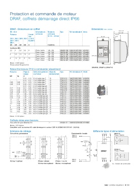
Protection et commande de moteur

          DRAF, coffrets démarrage direct IP66


          DRAF - Démarreurs en coffret                                           Dimensions mm, inches
                                                                                                         131.5  5.18"
          IEC - AC-3            Alimentation de   Tension de    Type   Réf. internationale @ Article     126.5  4.98"
          Puissance       Courant   commande  commande                                                60 2.36"
                          max.             Uc min ... Uc max                             107 4.22"    8 .32"
          220 V 380 V  500 V 690 V θ ≤ 40 °C
          230 V 400 V     Ue=400 V
          240 V
          kW  kW  kW  kW  A                V 50/60 Hz
          Coffrets IEC
          2.2  4  5.5  5.5  9   Phase / neutre  100...250  DRAF09-13N 1SBK134137R1300  H214453
                                Phase / phase  250...500  DRAF09-14P 1SBK134037R1400  H214484    230 9.06"
          3   5.5  7.5  7.5  12  Phase / neutre  100...250  DRAF12-13N 1SBK154137R1300  H214463
                                Phase / phase  250...500  DRAF12-14P 1SBK154037R1400  H214494  Ø 22.3 .88"
          4   7.5  9  9   18    Phase / neutre  100...250  DRAF16-13N 1SBK174137R1300  H214473
                                Phase / phase  250...500  DRAF16-14P 1SBK174037R1400  H214504
          Masse : 0.820 kg/pce
          Prévoir presse-étoupes Ø 20.
                                                                                 DRAF09, DRAF12, DRAF16
          Relais thermiques TF42 à commander séparément
          Puissance   Plage de   Calibre de la protection   Classe de   Type   Réf. internationale @ Article
                      réglage  court-circuit  déclenchement
          kW    Hp    A
          -     -     0.10 ... 0.13  0.5 A, fusible type T  10  TF42-0.13  1SAZ721201R1005  H439799
          -     -     0.13 ... 0.17  1.0 A, fusible type T  10  TF42-0.17  1SAZ721201R1008  H440469
          0.06  0.08  0.17 ... 0.23  1.0 A, fusible type T  10  TF42-0.23  1SAZ721201R1009  H439800
          0.09  0.12  0.23 ... 0.31  1.0 A, fusible type T  10  TF42-0.31  1SAZ721201R1013  H439801
          -     -     0.31 ... 0.41  2.0 A, fusible type gG  10  TF42-0.41  1SAZ721201R1014  H440471
          0.12  0.16  0.41 ... 0.55  2.0 A, fusible type gG  10  TF42-0.55  1SAZ721201R1017  H439802
          0.18  0.24  0.55 ... 0.74  4.0 A, fusible type gG  10  TF42-0.74  1SAZ721201R1021  H439803  2CDC231006V0013
          0.25  0.34  0.74 ... 1.00  6.0 A, fusible type gG  10  TF42-1.0  1SAZ721201R1023  H439804
          0.37  0.5   1.00 ... 1.30  6.0 A, fusible type gG  10  TF42-1.3  1SAZ721201R1025  H439805
          0.55  0.75  1.30 ... 1.70  10.0 A, fusible type gG 10  TF42-1.7  1SAZ721201R1028  H439806
          0.75  1.02  1.70 ... 2.30  10.0 A, fusible type gG 10  TF42-2.3  1SAZ721201R1031  H439807  TF42
          1.1   1.5   2.30 ... 3.10  10.0 A, fusible type gG 10  TF42-3.1  1SAZ721201R1033  H439808
          1.5   2.04  3.10 ... 4.20  20.0 A, fusible type gG 10  TF42-4.2  1SAZ721201R1035  H439809
          2.2   2.99  4.20 ... 5.70  20.0 A, fusible type gG 10  TF42-5.7  1SAZ721201R1038  H439810
          3     4.08  5.70 ... 7.60  35.0 A, fusible type gG 10  TF42-7.6  1SAZ721201R1040  H439811
          4     5.44  7.60 ... 10.0  35.0 A, fusible type gG 10  TF42-10  1SAZ721201R1043  H439812
          5.5   7.48  10.0 ... 13.0  40.0 A, fusible type gG 10  TF42-13  1SAZ721201R1045  H439813
          7.5   10.2  13.0 ... 16.0  40.0 A, fusible type gG 10  TF42-16  1SAZ721201R1047  H439814
          -     -     16.0 ... 20.0  63.0 A, fusible type gG 10  TF42-20  1SAZ721201R1049  H976497  L1 L2 L3  N
          Masse : 0.130 kg/pce
                                                                                              V
          Coffrets vides avec boutons                                                      U
          Avec sortie mm pour démarreur IEC  –        FR16AF-12  1SBN101337R1000 H214990
                                                                                        1  3  5        A1
          Masse : 0.53 kg/pce                                                          L1 L2 L3
          Compléter avec contacteur AF, relais thermique et contact CB5-10 (1SBN010013R1010 - 212104).    U c =    U s
                                                                                                       A2
          Schémas de câblage                                                     I  Différents types d'alimentation
                                                                                   U c
          Circuit de puissance                                     Commande locale     DRAF      N   DRAF..N
                                                                                          L1 L2 L3
                                                                DRAF..P                +             Phase / Neutre
                                                                DRAF..N  KM1: 5/L3              V
                                                                                O                      A1
                                                                                 R           U
                                                                          A             A                 U c  = V
                                                                        RESET        RESET 2  4  6
                                                                           M    95     T1 M T2 T3 3  95  5  A1
                                                                                          1
                                                                                          L1 L2  96 L3  A2
                                                                                96  FR1      FR1          U c =    U s
                                                                         STOP          STOP
                                                                             -7           -3           A2
                                                                                13    U c    13      DRAF..P
                                                                           I    KM1  I   I  DRAF KM1  Phase / Phase
                                                                             -8  14       -4  14
                                                                                                       A1
                                                                                A1  O        A1+       A1
                                                                             KM1    R     KM1             U c =    U
                                                                                A2           A2-          U c  = V
                                                                                          2  4  6
                                                                DRAF..N  N                T1 T2 T3     A2
                                                                                                       A2
          Moteur triphasé         Phase / phase   Phase / neutre  DRAF..P  KM1: 3/L2   -
                                  Moteur monophasé  Moteur monophasé                               Uc : tension de commande
                                                                                            ABB  Contrôle industriel  |  4/19  9
   932   933   934   935   936   937   938   939   940   941   942