
Page 295 - Railways Applications Terminal blocks
P. 295
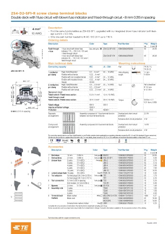
ZS4-D2-SF1-R screw clamp terminal blocks
         Double deck with 1 fuse circuit with blown fuse indicator and 1 feed-through circuit - 8 mm 0.315 in spacing


                                    Description
                        4 mm²
                                       – Find the same functionalities as ZS4-D2-SF1, upgraded with our integrated blown fuse indicator (with leak-
                        10 AWG        age current < 0.5 mA),
                                       – Only one part number needed to fit AC / DC 24 V up to 110 V.
                                    Ordering details
                                    Description                   Color     Type      Part Number        Pkg  Weight
                                                                                                         qty  (1 pce) g
                                    Feed-through   1 fuse circuit with blown fuse   Grey, dark grey  ZS4-D2-SF1-R3  1SNK508424R0000  50  29.40
                                1SNK161097V0014  1 feed-through circuit     ZS4-D2-SF1-R1  1SNK508423R0000  50  29.40
                                              indicator 115 ... 250 V AC / DC and
                                    + fuse
                                              1 fuse circuit with blown fuse
                                              indicator 24 ... 110 V AC / DC and 1
                                              feed-through circuit
                                    Main technical data                                Mounting instructions
                                    Connecting capacity           IEC       UL - CSA   Rail              TH 35-7.5,
                                                                                                         TH 35-15
         ZS4-D2-SF1-R
                                    1 conductor   Rigid: Solid/Stranded  0.2 ... 6 mm²  24 ... 10 AWG  Wire stripping   11 mm
                                    per clamp  Flexible without ferrule  0.22 ... 4 mm²  length          0.433 in
                                             Flexible with non insulated ferrule  0.22 ... 4 mm²  24 ... 12 AWG
                                             Flexible with insulated ferrule  0.22 ... 4 mm²  24 ... 12 AWG
                  89.2  3.51"
                                             Gauge                A3-B3
                                    2 conductors   Rigid: Solid/Stranded  0.2 ... 2.5 mm²  24 ... 14 AWG  Tool  Flat screwdriver
               180°
          90°  90°                  per clamp  Flexible without ferrule  0.2 ... 2.5 mm²                 Ø 3.5 mm
                                             Flexible with twin ferrule  0.22 ... 2.5 mm² 24 ... 14 AWG  Ø 0.138 in
          124.7  4.91"  109.7  4.32"  83  3.27"  68  2.68"  Disconnect circuit  6.3 A / 4 mm²  12 A / 10 AWG
                                    Rated current / Rated cross section
                                    Feed-through circuit
                                    Rated current / Rated cross section  32 A / 4 mm²  30 A / 10 AWG  Torque  0.6 Nm ± 0.1
                                                                                                         5.31  lb.in ± 0.885
                                    Rated voltage                 800 V     300 V
                     48.2  1.90"    Impulse withstand voltage     8000 V
                                    Protection                    IP20      NEMA 1
         8 mm 0.315 in spacing
                                    Separate               Assembly composed of 1 fuse terminal block in   Overload and short-circuit   2.5 W
                                    arrangement            between non fuse terminal blocks  protection
                                                                                      Exclusive short-circuit protection  4 W
                                    Compound               Assembly composed of 5 fuse terminal blocks  Overload and short-circuit   1.6 W
                                    arrangement                                       protection
                                                                                      Exclusive short-circuit protection  4 W

                                    The connecting capacity data for one Rigid: Solid/Stranded, or one Flexible conductor (when applicable) is a mandatory information required by IEC, UL and CSA standards (Copper conductors).
                                    All other data are provided as supplementary information only. For more details, please consult our CB, UL or CSA certificates and technical datasheet available on http://www.TE.com
                                      CE   CB  RoHS  USR  CSA  EAC                     BV  DNV
                                    Accessories
                                      Description                   Color   Type      Part Number        Pkg  Weight
         1           2
                                                                                                         qty  (1 pce) g
                                    1  End stops  10 mm   0.394 in   Dark grey  BAZH1  1SNK900102R0000   20    24.00
                                    2  End sections  2.5 mm   0.098 in  Dark grey  ES4-D2-SF1  1SNK508911R0000  20  5.00
                                    3  Jumper bars  2 poles   57 A (IEC)  Orange  JB8-2  1SNK908302R0000  50    2.70  8
         3           4                           3 poles   57 A (IEC)       JB8-3     1SNK908303R0000    50     4.10
                                                 4 poles   57 A (IEC)       JB8-4     1SNK908304R0000    50     5.60
                                                 5 poles   57 A (IEC)       JB8-5     1SNK908305R0000    40     7.00
                                                 10 poles   57 A (IEC)      JB8-10    1SNK908310R0000    20    14.20
                                    4  Lateral jumper bars 10 poles   35 A (IEC)  Grey  PC81-10  1SNA173523R1100  10  5.00
         5           6
                                    5  Test adapters  For test plugs DIA 2 mm 0.079 in  Dark grey  TP2  1SNK900203R0000  20  1.70
                                                 For test plugs DIA 4 mm 0.157 in  TP4  1SNK900205R0000  20     2.40
                                    6  Test connectors  5.2 mm 0.205 in spacing  Dark grey  TC5  1SNK900200R0000  10  5.20
                                                 End module, 5.2 mm 0.205 in  TC5-R1  1SNK900201R0000    10     5.20
         7           8              7  Spacers   2.8 mm   0.110 in   Dark grey  ES-TC8  1SNK900104R0000  10     1.40
                                    8  Assembly rods  2 poles               TGA8      1SNA168672R1100    10     1.00
                                                 3 poles                    TGA8      1SNA168673R1200    10     1.50
                                                 4 poles                    TGA8      1SNA168674R1300    10     2.00
                                    9  Terminal block   Blank marker   White  MG-CPM 13 41791 1SNB041791R0612  1680  0.27
         9
                                      markers    Blank card                 MC812     1SNK160000R0000    22    10.00
                                                                            MC812PA   1SNK169999R0000    20    14.00
                                                 Universal wire markers holder  Grey  UMH  1SNK900611R0000  10  0.20  1SNK161077S0201
                                    Complete list of accessories is indicated in the terminal block datasheet including end stops.
                                    Some accessories such as jumper bars may modify the terminal block's ratings: Complete information available in the accessories section of the catalog.


                                    Technical data valid for copper conductors only.
                                                                                                           PAGE 293