
Page 293 - Railways Applications Terminal blocks
P. 293
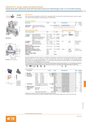
ZS4-D2-S-T screw clamp terminal blocks
         Double deck with 1 disconnect circuit with test socket screws and 1 feed-through circuit - 5.2 mm 0.205 in spacing


                                    Description
                        4 mm²
                                    Find the same functionalities as ZS4-D2-S, upgraded with the two built-in test socket screws meant to ease
                        10 AWG      your signal testing during commissioning and maintenance.

                                    Ordering details
                                    Description                   Color     Type      Part Number        Pkg  Weight
                                                                                                         qty  (1 pce) g
                                    Feed-through +  1 disconnect circuit with 2 test   Grey  ZS4-D2-S-T2  1SNK505316R0000  50  16.20
                                              socket screws and 1 feed-through
                             1SNK161099V0014  Main technical data                      Mounting instructions
                                    disconnect
                                              circuit
                                    Connecting capacity           IEC       UL - CSA   Rail              TH 35-7.5,
                                                                                                         TH 35-15
                                    1 conductor   Rigid: Solid/Stranded  0.2 ... 4 mm²  24 ... 10 AWG  Wire stripping   10.5 mm
                                    per clamp  Flexible without ferrule  0.22 ... 4 mm²  length          0.413 in
                                             Flexible with non insulated ferrule  0.22 ... 4 mm²  24 ... 12 AWG
         ZS4-D2-S-T
                                             Flexible with insulated ferrule  0.22 ... 2.5 mm² 24 ... 14 AWG
                                             Gauge                A3-B3
                                    2 conductors   Rigid: Solid/Stranded  0.2 ... 1.5 mm²  24 ... 16 AWG  Tool  Flat screwdriver
                                    per clamp  Flexible without ferrule  0.2 ... 1.5 mm²                 Ø 3.5 mm
             70.4  2.77"
                                             Flexible with twin ferrule  0.22 ... 1.5 mm² 24 ... 16 AWG  Ø 0.138 in
                                    Disconnect circuit
                                    Rated current / Rated cross section  25 A / 4 mm²  27 A / 10 AWG
                                    Feed-through circuit          29 A / 4 mm²  27 A / 10 AWG
                        78.6  3.09"  71.1  2.8"  84.8  3.34"  77.3  3.04"  Rated short-time withstand current (1s)  480 A  Torque  0.6 Nm ± 0.1
                                    Rated current / Rated cross section
                                                                                                         5.31  lb.in ± 0.885
                                    Rated voltage
                                    Impulse withstand voltage     630 V     300 V
                                                                  8000 V
                                    Protection                    IP20      NEMA 1
                36.77  1.45"        Recommendation for best usage: in horizontal assemblies, disconnect terminal blocks should be mounted
                                    with fixed foot on top (power side) so that the disconnect knife does not partially close through gravity.
         5.2 mm 0.205 in spacing
                                    Furthermore, as specified per IEC 60947-7-1, disconnect terminal blocks are intended to be used for temporary
                                    disconnection at zero potential and at no load.
                                    The connecting capacity data for one Rigid: Solid/Stranded, or one Flexible conductor (when applicable) is a mandatory information required by IEC, UL and CSA standards (Copper conductors).
                                    All other data are provided as supplementary information only. For more details, please consult our CB, UL or CSA certificates and technical datasheet available on http://www.TE.com
                                      CE   CB  RoHS  USR  CSA  EAC                     BV  DNV
                                    Accessories
                                      Description                   Color   Type      Part Number        Pkg  Weight
         1           2
                                                                                                         qty  (1 pce) g
                                    1  End stops  10 mm   0.394 in   Dark grey  BAZH1  1SNK900102R0000   20    24.00
                                    2  End sections  2.55 mm   0.100 in  Dark grey  ES4-D2  1SNK505960R0000  20  4.10
                                    3  Jumper bars  2 poles   32 A (IEC)  Orange  JB5-2  1SNK905302R0000  50    1.30
         3           4                           3 poles   32 A (IEC)       JB5-3     1SNK905303R0000    50     2.00
                                                 4 poles   32 A (IEC)       JB5-4     1SNK905304R0000    50     2.70
                                                 5 poles   32 A (IEC)       JB5-5     1SNK905305R0000    50     3.50
                                                 10 poles   32 A (IEC)      JB5-10    1SNK905310R0000    30     7.10
                                                 50 poles   32 A (IEC)      JB5-50    1SNK905350R0000    10    36.00
         5           6
                                    4  Test adapters  For test plugs DIA 2 mm 0.079 in  Dark grey  TP2  1SNK900203R0000  20  1.70  8
                                                 For test plugs DIA 4 mm 0.157 in  TP4  1SNK900205R0000  20     2.40
                                    5  Shield connectors                    SHB       1SNK900602R0000    20     4.90
                                    6  Terminal block   Blank marker   White  MG-CPM 13 41790 1SNB041790R0512  1960  0.23
                                      markers    Blank card                 MC512     1SNK140000R0000    22     9.00
                                                                            MC512PA   1SNK149999R0000    20    10.00
                                                 Universal wire markers holder  Grey  UMH  1SNK900611R0000  10  0.20
                                    Complete list of accessories is indicated in the terminal block datasheet including end stops.
                                    Some accessories such as jumper bars may modify the terminal block's ratings: Complete information available in the accessories section of the catalog.


                                                                                                                    1SNK161075S0201


                                    Technical data valid for copper conductors only.
                                                                                                           PAGE 291