
Page 289 - Railways Applications Terminal blocks
P. 289
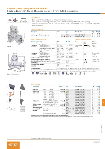
ZS6-D1 screw clamp terminal blocks
         Double deck with 1 feed-through circuit - 6 mm 0.236 in spacing


                                    Description
                        6 mm²
                                       – Ease one potential distribution on 4 independent screw clamps,
                        10 AWG         – Save space by connecting conductors up to 6 mm² 10 AWG in just 6 mm 0.236 in spacing,
                                       – Boost the performances: ZS6-D... with ES4-D2 end section is rated 1000 V DC IEC, perfectly adapted to
                                      solar applications.
                                    Ordering details
                                                                                                              Weight
                                    Description                   Color     Type      Part Number        Pkg  (1 pce) g
                             1SNK161009F0014  Feed-through  1 feed-through circuit  Grey  ZS6-D1  1SNK506211R0000  50  18.40
                                                                                                         qty
                                                                                      1SNK506214R0000
                                                                            ZS6-D1-RD
                                                                                                               18.40
                                                                                                         50
                                                                       Red
                                    Main technical data                                Mounting instructions
                                    Connecting capacity           IEC       UL - CSA   Rail              TH 35-7.5,
                                                                                                         TH 35-15
                                    1 conductor   Rigid: Solid/Stranded  0.2 ... 6 mm²  24 ... 10 AWG  Wire stripping   10 mm
         ZS6-D1                     per clamp  Flexible without ferrule  0.2 ... 6 mm²  length           0.393 in
                                             Flexible with non insulated ferrule  0.22 ... 4 mm²  24 ... 12 AWG
                                             Flexible with insulated ferrule  0.22 ... 4 mm²  24 ... 12 AWG
                                             Gauge                A4-B3
                70.4  2.77"         2 conductors   Rigid: Solid/Stranded  0.2 ... 2.5 mm²  24 ... 14 AWG  Tool  Flat screwdriver
                                    per clamp  Flexible without ferrule  0.2 ... 2.5 mm²                 Ø 4 mm
                                             Flexible with twin ferrule  0.22 ... 2.5 mm² 24 ... 14 AWG  Ø 0.157 in
                                    Rated current / Rated cross section  40 A / 6 mm²  30 A / 10 AWG
                                    Rated short-time withstand current (1s)  720 A     Torque            0.85 Nm ± 0.15
                            74.5  2.93"  67  2.64"  Short Circuit Current Rating (with specific conditions)  800 V  100 kA  7.52  lb.in ± 1.33
                                    Rated voltage
                                                                            300 V
                                    Impulse withstand voltage
                                                                  IP20
                                    Protection                    8000 V    NEMA 1
                                    Increased safety Ex e         440 V 40 A IEC/EN 60079-7 - IM2 II 2 GD Ex eb I/II/IIIC – 300 V 30 A UL 60079-7 - Class I, Zone 1, AEx e II, Ex e II U
                                    The connecting capacity data for one Rigid: Solid/Stranded, or one Flexible conductor (when applicable) is a mandatory information required by IEC, UL and CSA standards (Copper conductors).
                    36.8  1.45"     All other data are provided as supplementary information only. For more details, please consult our CB, UL or CSA certificates and technical datasheet available on http://www.TE.com
         6 mm 0.236 in spacing        CE   CB  RoHS  USR CNR  CSA  EAC Ex  ATEX  IECEx  BR-Ex e II  Haz Loc  BV  DNV  Rina


                                    Accessories
                                      Description                   Color   Type      Part Number        Pkg  Weight
         1           2
                                                                                                         qty  (1 pce) g
                                    1  End stops  10 mm   0.394 in   Dark grey  BAZH1  1SNK900102R0000   20    24.00
                                    2  End sections  2.55 mm   0.100 in  Dark grey  ES4-D2  1SNK505960R0000  20  4.10
                                    3  Jumper bars  2 poles   41 A (IEC)  Orange  JB6-2  1SNK906302R0000  50    1.30
         3           4                           3 poles   41 A (IEC)       JB6-3     1SNK906303R0000    50     2.10
                                                 4 poles   41 A (IEC)       JB6-4     1SNK906304R0000    50     2.90
                                                 5 poles   41 A (IEC)       JB6-5     1SNK906305R0000    50     3.60
                                                 10 poles   41 A (IEC)      JB6-10    1SNK906310R0000    20     7.40
                                    4  Test adapters  For test plugs DIA 2 mm 0.079 in  Dark grey  TP2  1SNK900203R0000  20  1.70
         5           6
                                                 For test plugs DIA 4 mm 0.157 in  TP4  1SNK900205R0000  20     2.40  8
                                    5  Test connectors  End module, 5.2 mm 0.205 in  Dark grey  TC5-R1  1SNK900201R0000  10  5.20
                                    6  Spacers   0.8 mm   0.031 in   Dark grey  ES-TC6  1SNK900105R0000  10     0.80
                                    7  Shield connectors                    SHB       1SNK900602R0000    20     4.90
         7           8              8  Terminal block   Blank marker   White  MG-CPM 13 41791 1SNB041791R0612  1680  0.27
                                      markers    Blank card                 MC612     1SNK150000R0000    22    10.00
                                                                            MC612PA   1SNK159999R0000    20    11.00
                                                 Universal wire markers holder  Grey  UMH  1SNK900611R0000  10  0.20
                                    Complete list of accessories is indicated in the terminal block datasheet including end stops.
                                    Some accessories such as jumper bars may modify the terminal block's ratings: Complete information available in the accessories section of the catalog.


                                                                                                                    1SNK161013S0201


                                    Technical data valid for copper conductors only.
                                                                                                           PAGE 287