Page 95 - Railways Applications Terminal blocks
P. 95

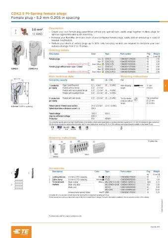
CDK2.5 PI-Spring female plugs
         Female plug - 5.2 mm 0.205 in spacing


                                    Description
                        2.5 mm²
                                       – Create your own female plug assemblies without any special tools, easily snap together multiple plugs for
                        12 AWG        optimal ergonomics and quick assembly,
                                       – Increase your flexibility: eliminate stock of pre-configured female plugs, easily add an extra plug in case of
                                      needed modification,
                                       – Reduce your stock of unitary plugs up to 30%: only two plug variants are required to compose your own
                                      subsets of plugs from 2 to 15 poles.
                    1SNK160291V0014  1SNK160292V0014  Ordering details  Color  Type   Part number        Pkg  (1 pce) g

                                    Description
                                                                                                              Weight
                                                                                                         50
                                    Female plugs                      Grey  CDK2.5    1SNK805712R0000    qty    2.80
                                                                      Blue  CDK2.5-BL  1SNK805742R0000   50     2.80
                                                 Available in Q3.2019  Green-Yellow  CDK2.5-PE  1SNK805750R0000  50  2.80
                                    Female plugs without outer nubs - Closed  Grey  CDK2.5-E  1SNK805713R0000  50  2.80
         CDK2.5      CDK2.5-E                                         Blue  CDK2.5-BL-E  1SNK805743R0000  50    2.80
                                                 Available in Q3.2019  Green-Yellow  CDK2.5-PE-E  1SNK805753R0000  50  2.80
                                    Main technical data                                Mounting instructions
           19.1  0.75"
                                    Connecting capacity           IEC       UL - CSA   Rail

                   21.1  0.83"      1 conductor   Rigid: Solid/Stranded  0.2 ... 4 mm²  26 ... 12 AWG  Wire stripping   11 mm  3
                                             Flexible without ferrule
                                                                                       length
                                    per clamp
                                                                  0.22 ... 2.5 mm²
                                                                                                         0.433 in
                                                                  0.22 ... 2.5 mm² 26 ... 14 AWG
                                             Flexible with non insulated ferrule
                     36.2  1.43"             Flexible with insulated ferrule  0.22 ... 2.5 mm² 26 ... 14 AWG
                                    2 conductors   Flexible with twin ferrule  0.22 ... 0.5 mm² 26 ... 20 AWG  Tool (for flexible   Flat screwdriver
                                    per clamp                                          conductor without   Ø 3.5 mm
                                                                                       ferrule)          Ø 0.138 in
         5.2 mm 0.205 in spacing    Rated current / Rated cross section  24 A / 2.5 mm²  22 A / 12 AWG
                                    Rated short-time withstand current (1s)  300 A
                                    Rated voltage                 1000 V    600 V
                                    Impulse withstand voltage     8000 V
                                    Protection                    IP20      NEMA 1
                                    The connecting capacity data for one Rigid: Solid/Stranded, or one Flexible conductor (when applicable) is a mandatory information required by IEC, UL and CSA standards (Copper conductors).
                                    All other data are provided as supplementary information only. For more details, please consult our CB, UL or CSA certificates and technical datasheet available on http://www.TE.com
                                      CE   CB  RoHS  USR CNR  CSA  EAC                 BV

                                    Mounting instructions
                                                                                                          15 poles max.


                                    Accessories
                                      Description                   Color   Type      Part number        Pkg  Weight
         1           2
                                                                                                         qty  (1 pce) g
                                    1  Locking devices  9.4 mm 0.370 in spacing  Black  VR-ZD  1SNK900637R0000  50  0.7
                                    2  Cable clamp  9.4 mm 0.370 in spacing  Dark grey  PT-ZD  1SNK900660R0000  50  1.04
                                    3  Terminal block   Blank marker   White  MG-CPM 13 41790 1SNB041790R0512  1960  0.23
         3                            markers    Blank strip label          MG-CPMFA 43196 1SNB043196R0012  350  2.56
                                                 Blank card                 MC512     1SNK140000R0000    22     9.00
                                                                            MC512PA   1SNK149999R0000    20    10.00
                                                 Universal wire markers holder  Grey  UMH  1SNK900611R0000  10  0.20
                                    Complete list of accessories is indicated in the terminal block datasheet including end stops.
                                    Some accessories such as jumper bars may modify the terminal block's ratings: Complete information available in the accessories section of the catalog.
                                                                                                                    1SNK164005S0201


                                    Technical data valid for copper conductors only.


                                                                                                            PAGE 93
   90   91   92   93   94   95   96   97   98   99   100