Page 141 - Motor_protection_and_control_Manual_motor_starters_ contactors
P. 141

DOL & reversing starters protected by thermal overload relays

         With AS, ASL contactors - open type version in kit form


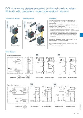
          Direct-on-line starters  Reversing starters                   Description
                                                                        You can easily assemble a direct-on-line starter by
                                        BER16C-3                        connecting AS or ASL contactors and T16 thermal
                                        Connection                      overload relay.
                                        set
                         AS                                             You can easily assemble reversing starter thanks to our
                         ASL
                         Contactors                                     complete range of accessories:
                                                                           – VM3 mechanical interlock unit: just clip it between the
                                                                         2 contactors without increasing starter length.
                                                                           – BER16C-3 connection set: it assures a safe and simple
                                                                         reversing connection between both contactor main
                                                  VM3                    terminals and an electrical interlocking between coil
                                                  Mechanical
                                                  interlock              and N.C. built-in auxiliary contact terminals of both   4
                                                  unit                   contactors.
                                     AS
                                     ASL
                                     Contactors                         Select now easily and quickly your starter in the fol-
                                                                        lowing pages at 400 V, up to 7.5 kW.
                                                                        For complete coordination tables, please contact your
                 T16                                  T16               ABB local sales organization.
                 Thermal overload relay               Thermal overload relay


         Wiring diagrams

            Direct-on-line starters
                                                     KM1:5/L3      KM1:5/L3            +             +

                                                     Us               Us
                          1/L1  3/L2  5/L3  1/L1  3/L2  5/L3  RESET  A  RESET  A  95  RESET  A    RESET  A   95
                       A1      13            13        M       95    M                 M       95    M
                    KM1                               STOP      FR1  STOP    96  FR1  STOP     FR1  STOP     96  FR1
                       A2      14            14                96                              96
                          2/T1  4/T2  6/T3  2/T1  4/T2  6/T3            O                              O
                                                               13             13               13            13
                                                           I  KM1       I   KM1           I  KM1       I   KM1
                                                               14             14               14            14
                A
             RESET
                M      95  97
                               FR1           FR1
               TEST    96  98                                KM1  A1       KM1  A1          KM1  A1+       KM1  A1+
               STOP       2/T1  4/T2  6/T3  2/T1  4/T2  6/T3  Us N  Us N
                                                               A2             A2               A2-           A2-

                                                     KM1:3/L2      KM1:3/L2            -             -
                            V
                          U  W          U  V
               Power circuit  M  1-phase  M         AC local control  AC remote control  DC local control  DC remote control
                            ~
                                         ~
           Reversing starters
                                             KM1:5/L3         KM1:5/L3         +               +
                                                   RESET A          RESET A           RESET A        RESET A
                                             Us      M   95   Us      M    95           M    95        M    95
                   1/L1  3/L2  5/L3  1/L1  3/L2  5/L3    96 FR1            96 FR1            96  FR1        96 FR1
                A1     21  13   A1     21  13       STOP             STOP              STOP           STOP
             KM1             KM2                                O                                O
                A2     22  14   A2     22  14
                   2/T1  4/T2  6/T3  2/T1  4/T2  6/T3         II     13    13                  II     13    13
                                                                    KM1  KM2                         KM1  KM2
                                                    13   13          14    14        13      13       14    14
                                                I  KM1  II   KM2  I               I  KM1  II   KM2  I
                                                    14   14                          14      14
                                                    22   22          22    22        22      22       22    22
                          A                       KM2   KM1         KM2  KM1        KM2    KM1       KM2   KM1
                       RESET  M  95  97             21   21          21    21        21      21       21    21
                                       FR1   Us     A1   A1  Us    KM1  A1  A1  KM2  A1+     A1+    KM1  A1+  A1+  KM2
                        TEST    96  98       N    KM1  A2  A2  KM2  N  A2  A2      KM1  A2-  A2-  KM2  A2-  A2-
                        STOP       2/T1  4/T2  6/T3  KM1:3/L2  KM1:3/L2        -               -
                                                                                                                    1SBC101275S0201
                                     V  W
                                   U
                       Power circuit         AC local control  AC remote control  DC local control  DC remote control
                                    M
                                    ~
                                                                                                          ABB  |  4/21
   136   137   138   139   140   141   142   143   144   145   146