Page 145 - Motor_protection_and_control_Manual_motor_starters_ contactors
P. 145

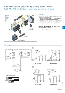
Star-delta starters protected by thermal overload relays

         With AS, ASL contactors - open type version in kit form


                                                                        Description
                                                            Timer
                         BEY16C-3                                       You can easily assemble a star-delta starter thanks to our
                         Connection set                                 complete range of accessories:
                                         KM2                               – VM3 mechanical interlock unit: just clip it between the
            L     Y
                                                                         2 contactors without increasing starter length.
                                                                           – BEY16C-3 connection set: it assures a safe and simple
                                                                         connection between contactors main terminals and an
                          KM3                                            electrical interlocking between coil and N.C. built-in
                      KM1                                                auxiliary contact terminals of star and delta contactors.


                                        VM3                             Select now easily and quickly your starter in the fol-
                                        Mechanical                      lowing pages at 400 V, up to 11 kW.         4
                                        interlock unit  CA3
                                                       1-pole auxiliary
                  AS                                   contact block    For complete coordination tables, please contact your
                  ASL
                  Contactors                                            ABB local sales organization.


                                             BEY16C-3
                                             Connection set

                                  T16
                                  Thermal overload relay


         Wiring diagrams


                                                            KM1:5/L3                   KM1:5/L3
                                                                    A                             A
                                                                 RESET                         RESET M
                                                            Us      M    95            Us              95  O
                       1/L1  3/L2  5/L3  13  23  1/L1  3/L2  5/L3  21  1/L1  3/L2  5/L3  13  21  STOP  96  FR1  STOP  96  FR1
                     A1              A1         A1                       23                         KM1  23  I
                  KM1             KM3         KM2                I     KM1                             24
                     A2              A2         A2                       24
                       2/T1  4/T2  6/T3  14  24  2/T1  4/T2  6/T3  22  2/T1  4/T2  6/T3  14  22  17    17
           RESET A                                                     KT                        KT
              M     95  97                                                28   18                   28   18
                           FR1                                     13  13  22  22            13  13  22  22
             TEST   96  98                                        KM2KM1  KM2  KM3          KM2KM1  KM2  KM3
             STOP      2/T1  4/T2  6/T3                     Us     14  14  21  21      Us    14  14  21  21
                                                            N        A1   A1   A1   A1  N     KM1  A1  KM3  A1  A1  KM2KT  A1
                                                                   KM1  KM3     KM2  KT
                                                            KM1:3/L2  A2  A2   A2   A2  KM1:3/L2  A2  A2  A2  A2
                                                                     L         Y               L         Y
                                                                  AC local control           AC remote control
                            W1      W2
                            V1      V2
                            U1      U2
                            W1      W2                      +                          +
                            V1      V2                         RESET  M A  95                 RESET  A
                            U1      U2                                                          M     95
                                                                        96  FR1                       FR1
                                                                 STOP                    O            96
                                                                                               STOP
                                                                        23
                                                              I       KM1                 I           23
                                                                        24                          KM1
                                                                                                      24
            Function diagram Electronic Timer                      KT    17                           17
                                                                                                KT
             A1-A2                                                    28   18                      28   18
                                                                13  13  22  22
                                                                                            13
             17-18                                            KM2  KM1  KM2  KM3          KM2 KM1  13  KM2  22  KM3 22
             17-28                                              14  14  21  21              14  14  21  21
           green LED                                              A1+  A1+  A1+  A1+          A1+  A1+  A1+   A1+
                   t1   t2                                     KM1  A2-  KM3  A2-  A2-  KM2 KT  A2-  KM1  A2-  KM3  A2-  A2-  KM2  KT  A2-
                                                            -                          -
                                                                                                                    1SBC101288S0201
                t1 = adjusted starting time                       L        Y                  L         Y
                t2 = transition time (50ms)
                                                                  DC local control           DC remote control
                                                                                                          ABB  |  4/25
   140   141   142   143   144   145   146   147   148   149   150