Page 216 - Motor_protection_and_control_Manual_motor_starters_ contactors
P. 216

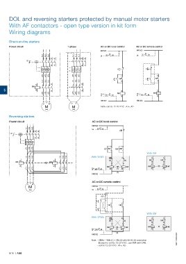
DOL and reversing starters protected by manual motor starters

       With AF contactors - open type version in kit form
       Wiring diagrams


       Direct-on-line starters
       Power circuit                        1-phase              AC or DC local control  AC or DC remote control
                                                                 KM1:5/L3               KM1:5/L3
                             1/L1  3/L2  5/L3   1/L1  3/L2  5/L3  Us  33  Q1  34        Us  33  Q1  34
                                  33  43              33  43
                  Q1
                                  34  44              34  44
                            I> I> I>           I> I> I>                     O                 O
                             2/T1  4/T2  6/T3   2/T1  4/T2  6/T3               13                     13
                                                                         I   KM1              I     KM1
                             1/L1  3/L2  5/L3   1/L1  3/L2  5/L3               14                     14
                        A1        13                  13
                     KM1
    5                   A2        14                  14                       A1                     A1
                             2/T1  4/T2  6/T3   2/T1  4/T2  6/T3  Us   Q1   KM1          Us   Q1   KM1
                                                                  N  43  44    A2        N  43  44    A2
                                                                  KM1:3/L2               KM1:3/L2
                              V
                            U   W              U  V
                              M                M                  Note: coil Uc 12-20 V DC : A1+, A2-
                              ~
                                               ~
       Reversing starters
       Power circuit                                        AC or DC local control
                                                            KM2:5/L3

                  1/L1  3/L2  5/L3                          Us  33  Q1  34
                        33  43                                               O
        Q1
                        34  44
                 I> I> I>
                  2/T1  4/T2  6/T3                                  I  KM1  .3  II   KM2  .3
                                                                        .4      .4
                                                                                               With VM
                  1/L1  3/L2  5/L3      1/L1  3/L2  5/L3    With VEM4  01      01                  21     21
              A1                    A1                                 (2)       (2)            KM2     KM1
           KM1                   KM2                                                               22     22
                                                                                                  A1     A1
              A2                    A2                               KM1          KM2           KM1         KM2
                  2/T1  4/T2  6/T3      2/T1  4/T2  6/T3    Us  43  Q1  44  A2  (1)  A2           A2     A2
                                                            N
                                                                            (3)
                                                            KM2:3/L2
                                                            AC or DC remote control
                  U  V  W
                   M                                        KM2:5/L3 33  Q1  34
                   ~

                                                            Us
                                                                  O
                                                               II
                                                                        .3      .3
                                                                      KM1    KM2
                                                                        .4      .4
                                                               I
                                                                                               With VM
                                                            With VEM4
                                                                       01      01                  21     21
                                                                       (2)      (2)             KM2     KM1
                                                                                                   22     22
                                                                                                  A1     A1
                                                                     KM1         KM2            KM1         KM2
                                                               Us  43  Q1  44  A2  (1)  A2        A2     A2
                                                            N
                                                                           (3)
                                                            KM2:3/L2
                                                            Note:  - VEM4 = VM4 (1) + VE4 (2) with A2-A2 (3) connection  1SBC101918S0201
                                                                 (Except for coil Uc 12-20 V DC : use VM4 with CA4).
                                                               - coil Uc 12-20 V DC : A1+, A2-
       5/16  |  ABB
   211   212   213   214   215   216   217   218   219   220   221