
Page 34 - Current & voltage sensors catalog
P. 34
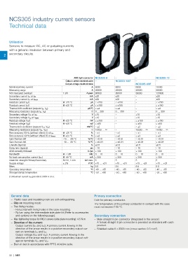
NCS305 industry current sensors
       Technical data


       Utilisation
       Sensors to measure DC, AC or pulsating currents
       with a galvanic insulation between primary and
    2  secondary circuits.


                                                ABB 8 pin connector NCS305-6  –        –            NCS305-10
                                           Output current shielded cable –  NCS305-6AF  –           –
                                          Output voltage shielded cable –  –           NCS305-6VF   –
       Nominal primary current                             A  6000        6000         6000         10000
       Measuring range                                     A  20000       20000        20000        30000
       Not measured overload             1 s/h          A peak  80000     80000        80000        120000
                                                          mA  ±20         ±20          –            ±20
       Secondary current I S1 at I PN
                                                          mA  ±20         ±20          –            ±20
       Secondary current I S2 at I PMAX
       Residual current I S10            @ +25 °C         μA ≤ ±250       ≤ ±250       –            ≤ ±250
       Residual current I S20            @ +25 °C         μA ≤ ±180       ≤ ±180       –            ≤ ±180
       Thermal drift coefficient (outputs I S1, I S2)   μA/°C ≤ ±4        ≤ ±4         –            ≤ ±4
       Measuring resistance (outputs I S1, I S2)           Ω 0 … 350      0 … 350      –            0 … 350
                                                           V  ±10         –            ±10          ±10
       Secondary voltage V S1 at I PN
                                                           V  ±10         –            ±10          ±10
       Secondary voltage V S2 at I PMAX
       Residual voltage V S10            @ +25 °C         mV ≤ ±100       –            ≤ ±100       ≤ ±100
       Residual voltage V S20            @ +25 °C         mV ≤ ±50        –            ≤ ±50        ≤ ±50
       Thermal drift coefficient (outputs V S1, V S2)   mV/°C ≤ ±2        –            ≤ ±2         ≤ ±2
       Measuring resistance (outputs V S1, V S2)           Ω 10000 … ∞    –            10000 … ∞    10000 … ∞
                                         @ +25 °C          % ≤ ±1         ≤ ±1         ≤ ±1         ≤ ±1
       Rms accuracy 50 Hz (without offset) (1) at I PN
       Rms accuracy 50 Hz (without offset) (1) at I PMAX  @ +25 °C  % ≤ ±3  ≤ ±3       ≤ ±3         ≤ ±3
       Gain thermal drift                -20 ... +85 °C  %/°C ≤ ±0.01     ≤ ±0.01      ≤ ±0.01      ≤ ±0.01
       Gain thermal drift                -40 ... -20 °C  %/°C ≤ ±0.04     ≤ ±0.04      ≤ ±0.04      ≤ ±0.04
       Linearity (typical)                                 % ±0.5         ±0.5         ±0.5         ±0.5
       Delay time (typical)                                μs ≤ 10        ≤ 10         ≤ 10         ≤ 10
       di/dt correctly followed                          A / μs ≤ 100     ≤ 100        ≤ 100        ≤ 100
       Bandwidth                         @ -1 dB          kHz 0 … 10      0 … 10       0 … 10       0 … 10
       No load consumption current (I A0+)  @ -40 °C      mA ≤ 300        ≤ 300        ≤ 300        ≤ 300
       Dielectric strength Primary/Secondary  50 Hz, 1 min  kV r.m.s. 5   5            5            5
       Supply voltage                    ± 2%            V DC +15 … +24   +15 … +24    +15 … +24    +15 … +24
       Mass                                               kg 5.5          5.8          5.8          5.5
       Operating temperature                              °C -40 … +85    -40 … +85    -40 … +85    -40 … +85
       Storage/startup temperature                        °C -50 … +90    -50 … +90    -50 … +90    -50 … +90
       (1) Maximum current I PN generated: 5000 A r.m.s.


        General data                                         Primary connection
           – Plastic case and insulating resin are self-extinguishing.   Hole for primary conductor.
           – Clip on mounting mode                           The temperature of the primary conductor in contact with the case
           – Two fixing modes:                                must not exceed 100 °C.
            - Horizontal with fixing holes in the case moulding.
            - By bar using the intermediate side plate kit (Refer to accessories
           and options on the following page).               Secondary connection
           –  Max tightening torque for M6.3 screws (side plate mounting): 4.5 N.m    – Male straight 8 pin connector (integrated in the sensor)
           –  Direction of the current:                       A female straight 8 pin connector is provided as standard with each
            - Output current (I S1 and I S2): A primary current flowing in the   product.
           direction of the arrow results in a positive secondary output cur-    – Shielded cable 6 x 2000 mm (cross section 0.5 mm²).
           rent on terminals I S1 and I S2.
            - Output voltage (V S1 and V S2): A primary current flowing in the
           direction of the arrow results in a positive secondary output volt-
           age on terminals V S1 and V S2.
           – Burn-in test in accordance with FPTC 404304 cycle.


       32  |  ABB