
Page 92 - Current & voltage sensors catalog
P. 92
Glossary
Description of the main current and voltage sensor's characteristics
Nominal primary current (I PN) and nominal primary voltage (U PN)
This is the maximum current or voltage that the sensor can continuously withstand (i.e. without time limit).
The sensor is thermally sized to continuously withstand this value.
For alternating currents, this is the r.m.s. value of the sinusoidal current.
The value given in the catalogue or in the technical data sheet is a nominal rating value. This figure can be higher if certain conditions (temperature,
supply voltage…) are less restricting.
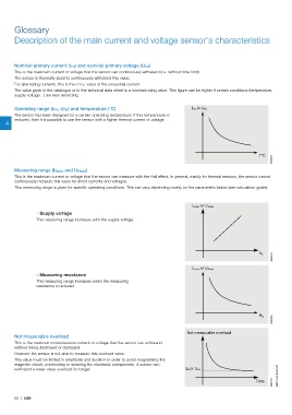
Operating range (I PN, U PN) and temperature (°C) I PN or U PN
The sensor has been designed for a certain operating temperature. If this temperature is
reduced, then it is possible to use the sensor with a higher thermal current or voltage.
4
T°C
G0249DG
Measuring range (I PMAX and U PMAX)
This is the maximum current or voltage that the sensor can measure with the Hall effect. In general, mainly for thermal reasons, the sensor cannot
continuously measure this value for direct currents and voltages.
This measuring range is given for specific operating conditions. This can vary depending mainly on the parameters below (see calculation guide).
I Pmax or U Pmax
- Supply voltage
The measuring range increases with the supply voltage.
G0208DG
V A
I Pmax or U Pmax
- Measuring resistance
The measuring range increases when the measuring
resistance is reduced.
G0209DG
R M
Not measurable overload
Not measurable overload
This is the maximum instantaneous current or voltage that the sensor can withstand
without being destroyed or damaged.
However the sensor is not able to measure this overload value.
This value must be limited in amplitude and duration in order to avoid magnetising the
magnetic circuit, overheating or straining the electronic components. A sensor can
withstand a lower value overload for longer. I PN or U PN
G0210DG
Time 1SBC140065S0201
90 | ABB