
Page 95 - Current & voltage sensors catalog
P. 95
Electronic current sensors
Instructions for mounting and wiring NCS sensors
Introduction
These instructions are a non-exhaustive synthesis of the main recommendations for mounting electronic current sensors. Each application configura-
tion is different, please do not hesitate to contact us for advice adapted to your particular case. Please note that incorrect or non-judicious use of
the sensor may lead to deterioration in the performance or operation of the sensor.
1 - Wiring diagram
– Direction of the current:
- Output current (I S1 and I S2): A primary current flowing in the direction of the arrow results in a positive secondary output current on the
terminals I S1 and I S2.
- Output voltage (V S1 and V S2): A primary current flowing in the direction of the arrow results in a positive secondary output voltage on the
terminals V S1 and V S2.
– Supply voltage: bipolar voltage -V A … 0 V … +V A (0…+V A for the NCS305).
4
It is possible to design electronic current sensors, upon request, that can operate with a unipolar supply voltage (-V A … 0 V ou 0 V …+V A).
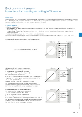
1.1 Sensors with connector output (current and voltage outputs)
NCS sensor Power supply
+ V A + V A
0V 0V
- V A - V A
I s1
Sensor internal electric connection I s1 R M1
V M1
I s2
I s2 R M2
V M2
V s1 R M3
I p
V M3
R M4
V s2
V M4 G0220DG
0V
1.2 Sensors with cable output (current outputs) NCS sensor Power supply
NCS sensors have two current outputs as standard: + V A + V A
–I S1 that supplies ±20 mA (peak) at ±I PN (peak) I s1
–I S2 that supplies ±20 mA (peak) at ±I PMAX (peak) I s1 R M1
V M1
Two measured gains are thus available. 0V 0V
V M2
In the case of a current output, R M is determined in the following manner: I s2 I s2 R M2
R M = V M / I S where V M = to be obtained at the terminals of R M
0V
I S = I S1 or I S2 (current output) I p
- V A - V A G0221DG
Limitation: 0 Ω < R M < 350 Ω for I S max (peak) of ±20 mA
The secondary cable passes through the white plastic enclosure
(included) containing a ferrite core (NCS125 & NCS165), to reduce the
interference that could affect the correct functioning of the sensor.
1.3 Sensors with cable output (voltage outputs) NCS sensor Power supply
The sensors have two voltage outputs as standard: + V A + V A
–V S1 that supplies ±10 V (peak) at ±I PN (peak)
V s1 R M3
–V S2 that supplies ±10 V (peak) at ±I PMAX (peak) V s1
0V 0V
Two measured gains are thus available.
V s2
In the case of a voltage output, R M is either greater than or equal to 10 kΩ. V s2 R M4
The secondary cable passes through the white plastic enclosure (included) 0V
containing a ferrite core (NCS125 & NCS165), to reduce the interference I p
that could affect the correct functioning of the sensor. - V A - V A G0222DG
1SBC140068S0201
ABB | 93