
Page 100 - Current & voltage sensors catalog
P. 100
Electronic voltage sensors
Instructions for mounting and wiring VS sensors
3 - Precautions to be taken into account, relative to the electromagnetic environment
– Best performance is obtained in an environment with low electromagnetic interference.
– Electromagnetic interference is generated by the switching of strong currents (e.g.: switch relay), high voltage switchgear
(e.g.: semi-conductor choppers), high intensity radio environment (e.g.: radio communication equipment).
– With the aim of minimising the effects of strong electromagnetic interference, please refer to standard rules (current working practice)
and especially the following:
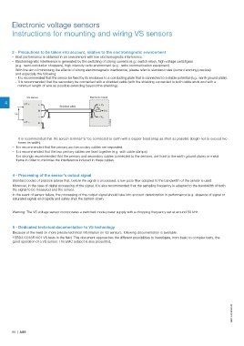
- It is recommended that the sensor be fixed by its enclosure to a conducting plate that is connected to a stable potential (e.g.: earth ground plate).
- It is recommended that the secondary be connected with a shielded cable (with the shielding connected to both cable ends and with a
minimum length of wire as possible extending beyond the shielding).
VS sensor Electronic board
4 HT +
+
Shielded cable + V A
R M
M 0 V
U P
– – V A
G0199DG
HT –
E
- It is recommended that the screen terminal "E" be connected to earth with a copper braid strap as short as possible (length not to exceed five
times its width).
– It is recommended that the primary and secondary cables are separated.
– It is recommended that the two primary cables are fixed together (e.g. with cable clamps).
– It is strongly recommended that the primary and secondary cables connected to the sensors, are fixed to the earth ground plates or metal
frame in order to minimise the interference induced in these cables.
4 - Processing of the sensor's output signal
Standard codes of practice advise that, before the signal is processed, a low-pass filter adapted to the bandwidth of the sensor is used.
Moreover, in the case of digital processing of the signal, it is also recommended that the sampling frequency is adapted to the bandwidth of both
the signal to be measured and the sensor.
In the event of sensor failure, the processing of the output signal should take into account deterioration in performance (e.g. absence of signal or
saturated signal) and rapidly and safely shut the system down.
Warning: The VS voltage sensor incorporates a switched mode power supply with a chopping frequency set at around 50 kHz.
5 - Dedicated technical documentation to VS technology
Because of the need on more precise technical information on VS sensors, following documentation is available:
1SBD370318R1001 VS tests in the field. This document approaches the different possibilities to investigate, from basic to complex tests, the
good operation of a VS sensor. The EMC subject is also presented.
1SBC140069S0201
98 | ABB