
Page 103 - Current & voltage sensors catalog
P. 103
Calculation guide
Closed loop Hall effect current sensors
ES, CS, MP and EL sensors
1 - Reminder of the key elements (closed loop Hall effect)
Formulas Abbreviations
1SBC146057V0014 N P x I P = N S x I S N P : turn number of the primary winding
I P : primary current
I PN : nominal primary current
V A = e + V S + V M
N S : turn number of the secondary winding
V S = R S x I S
I S : output secondary current
V A : supply voltage
ES300C V M = R M x I S
e : voltage drop across output transistors
(and in the protection diodes, if relevant) 4
V S : voltage drop across secondary winding
V M : measuring voltage
R S : resistance of the secondary winding
R M : measuring resistance
Values of "e" with a bipolar sensor supply
Sensor ES100 ES300…ES2000 CS300…CS1000 CS2000 MP or EL
Voltage "e" 2.5 V 1 V 2.5 V 1.5 V 3 V
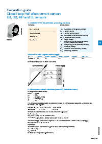
Reminder of the sensor electrical connection
Current sensor Power supply
+ + V A
I S R M
M 0 V
V M
– – V A
G0196DG
I P
G0196DG
2 - Measurement circuit calculation (secondary part of the sensor)
Example with ES300C sensor
N P/N S = 1/2000
I PN = 300 A
R S = 33 Ω (at +70 °C)
I S = 0.15 A (at I PN)
e = 1 V
2.1 - What load resistance (RM) is required to obtain an 8 V measuring signal (VM = 8 V) when the
IP current = 520 A peak?
I S = (N P / N S) x I P = (1 / 2000) x 520 = 0.26 A peak
R M = V M / I S = 8 / 0.26 = 30.77 Ω
We must check that the sensor can measure these 520 A peak, i.e.:
V A > e + V S + V M
If V A = ±15 V (±5%), then we must check that
15 x 0.95 > 1 + (33 x 0.26) + 8 which is false since 14.25 V< 17.58 V
Therefore a supply greater than or equal to 17.58 V must be selected. Select a ±24 V (±5%) supply.
We verify that 24 x 0.95 > 17.58 V.
Conclusion
An ES300C sensor can measure a peak of 520 A in the following conditions:
V A = ±24 V (±5%)
R M = 30.77 Ω 1SBC140071S0201
to obtain an 8 V signal at a peak of 520 A
ABB | 101