Page 106 - Current & voltage sensors catalog
P. 106

Calculation guide
       Electronic technology current sensors NCS sensors


                                  1 - Reminder of the key elements
                                  Formulas                             Abbreviations

                                                                        I P  : primary current
                                                                        I PN    :  nominal primary current
                                    V M1 = R M1 x I S1
                                                                        I PMAX   :  maximum primary current
                                                                        I S1   :  secondary current at I PN
                             1SBC146045V0014  with 0 Ω < R M1 or R M2 < 350 Ω  I S2   :  secondary current at I PMAX
                                    V M2 = R M2 x I S2
                                                                        V S1
                                                                             :  secondary voltage at I PN
    4                                                                   V S2   :  secondary voltage at I PMAX
                                                                             :
                                                                               supply voltage
                                                                        V A
                                                                        V M  :  measuring voltage
                                                                        R M  : measuring resistance
       NCS125-10
                                                                        R MMIN  :  minimum measuring resistance
                                                                        R MMAX  :  maximal measuring resistance
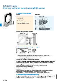
                                  Reminder of the sensor electrical connection

                                          NCS sensor              Power supply
                                                      + V A         + V A
                                                      0V            0V
                                                      - V A         - V A
                                                          I s1
                                                      I s1   R M1
                                                            V M1
                                                          I s2
                                                      I s2   R M2
                                                            V M2
                                                      V s1   R M3
                                    I p
                                                            V M3
                                                      V s2   R M4
                                                            V M4          G0220DG
                                                      0V
                                  2 - Measurement circuit calculation (current output)
                                  Example with NCS125-4 sensor
                                  I PN   = 4 000 A        I S1 @ I PN  = ±20 mA
                                  I PMAX   = 20 000 A     I S2 @ I PMAX = ±20 mA
                                  R M    = 0 - 350 Ω (I S1 & I S2)   V S1 @ I PN  = ±10 V
                                  R M    > 10 kΩ (V S2 & V S2)   V S2 @ I PMAX = ±10 V
                                  V A    = ±15 V ... ±24 V
                                     The design of the sensor requires that 2 operating points are respected on the outputs I S1 and I S2:
                                       • A maximum measuring voltage of 7 V DC (V MMAX ≤ R MMAX x I SMAX)
                                       • A maximum output current of ±20 mA DC.
                                  The supply voltage does not have any influence on the output signals.
                                  2.1 - What load resistance (R M) is required to obtain a 5 V measuring (V M = 5 V) when the current I P = 6000 A peak?
                                  The measured current is greater than I PN (4000 A for a NCS125-4), I S2 is therefore used as the measuring signal.
                                  Firstly the output current on I S2 must be calculated when I PN = 6000 A DC
                                  I S2 = I PN / I PMAX x I SMAX = 6000 / 20000 x 20 = 6 mA (correct because I S2MAX = ±20 mA DC)
                                  Now determine the value of the resistance R M
                                  R M = V M / I S2   = 5 / 0.006   = 833.33 Ω
                                  Conclusion
                                  The NCS125-4 sensor can measure 6000 A peak on the signal output I S2 with a resistance of 416.67 Ω
                                  (greater than 350 Ω) because the output current is smaller than I SMAX i.e. 20 mA DC
                                  The product of R M x I SMAX must always be smaller than or equal to maximum output of 7 V DC

                                  3 - Measurement circuit calculation (voltage output)
                                  No special calculation needs to be made. This NCS sensor range supplies a voltage directly proportional to
                                  the primary current I P between -10 V and +10 V. A load resistance of a value greater than or equal to 10 kΩ   1SBC140072S0201
                                  adapts the impedance of the measured output (V S1 or V S2) to the acquisition system.


       104  |  ABB
   101   102   103   104   105   106   107   108   109   110   111