
Page 107 - Current & voltage sensors catalog
P. 107
Calculation guide
Electronic technology voltage sensors VS sensors
1 - Reminder of the key elements
Formulas Abbreviations
1SBC146038V0014 V M = R M x I S and U PN = U P U P : primary voltage
U PN : nominal primary voltage
I SN I S I S : secondary current
VS1000B
VS50 ... VS1500: I SN : nominal secondary current
V A : supply voltage
● R M = [(0.8 x V AMIN) / I S] – 55
V AMIN : V A less lowest supply tolerance
● U HT+ + U HT- < 4.2 kV peak and
V M : measuring voltage
I
I U HT+ - U HT- < U PMAX R M : measuring resistance 4
VS2000 ... VS4200 :
● R M = [(0.8 x V AMIN) / I S] – 60
● U HT+ + U HT- < 10 kV peak and
I
I U HT+ - U HT- < U PMAX
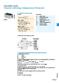
Reminder of the sensor electrical connection
VS sensor Power supply
HT + + + V A
R M
I S
M 0 V
U P
V M
– – V A
HT – G0193DG
G0193DG
2 - Measurement circuit calculation (secondary part of the sensor)
Example with VS1000B sensor
U PN = 1000 V
I SN = 50 mA
V A = ±24 V (±5%)
U PMAX = 1500 V
2.1 - What load resistance (RM) is required to obtain a 10 V measuring signal (VM = 10 V) when the
voltage U PMAX = 1500 V peak?
I S = I SN x U PMAX / U PN = 0.050 x 1500 / 1000 i.e. I S = 75 mA
R M = V M / I S = 10 / 0.075 i.e. R M = 133.33 Ω
We must check that the sensor can measure this 1500 V with a ±24 V (±5%) supply
V AMIN = 24 x 0.95 = 22.8 V
R M = [(0.8 x V AMIN) / I S] – 55 = [(0.8 x 22.8) / 0.075] – 55 i.e. R M = 188.2 Ω
We therefore verify that the sensor can measure this 1500 V voltage since the measuring resistance with
a ±24 V (±5%) supply is 188.2: for 133.33: required.
Conclusion
A VS1000B sensor can measure a peak of 1500 V in the following conditions:
V A = ±24 V (±5%)
1SBC140073S0201
R M = 133.33 Ω
to obtain a 10 V signal at 1500 V peak.
ABB | 105