
Page 101 - Current & voltage sensors catalog
P. 101
Electronic voltage detectors
Instructions for mounting and wiring VD detectors
Introduction
These instructions are a non-exhaustive synthesis of the main recommendations for mounting VD voltage detectors.
Each application configuration is different, please do not hesitate to contact us for advice adapted to your particular case.
Please note that incorrect or non-judicious use of the sensor may lead to deterioration in the performance or operation of the sensor.
1 - Wiring diagram
The VD voltage detector is a very reliable product, consequently the wiring is an important point to take into account.
The following points must be respected:
– The VD voltage detector connections wires must be dedicated to High Voltage only,
– The 4 screws used must respect the following specification:
- M5x7 insert for connections : screw M5 with flat washer. Tightening torque: 2 Nm. 4
It is also recommended that the LED (Light Emitting Diode) lenses are only removed during maintenance operations by qualified personnel.
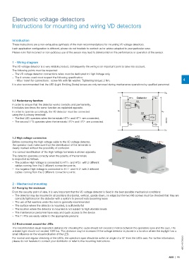
U P+
HT1+ Detector HT2+
1.1 Redundancy function
In order to ensure that the detector works correctly and permanently, PCB
it includes two times the same function as explained opposite.
In order to operate accordingly, the VD detector must be connected U P U P
using the 4 primary terminals:
– The first LED operates when the terminals HT1+ and HT1- are connected, PCB
– The second LED operates when the terminals HT2+ and HT2- are connected. G0216DG
HT1- HT2-
U P-
HT2-
1.2 High voltage connection
Before connecting the high voltage cable to the VD voltage detector, HT1+
the operator must make sure that the identification of the terminals is
clearly marked without the possibility of confusion.
HT2+
The correct identification of the High Voltage terminals is shown opposite:
The detector operates correctly when the polarity of the terminals
HT1-
is respected as follows:
– The positive High Voltage is connected to HT1+ and HT2+ with 2 different
cables coming from the 2 different connection points,
– The negative High Voltage is connected to HT1- and HT2- with 2 different
cables coming from the 2 different connection points.
2 - Mechanical mounting
2.1 Fixing by the enclosure
From the security point of view, it is very important that the VD voltage detector is fixed in the best possible mechanical conditions:
– The detector may be mounted in all positions (horizontal, vertical, upside down, on edge) but the two M6 screws must be checked that they are
correctly tightened on the detector with a system to prevent nuts becoming loose
– The use of flat washers under the nuts is generally recommended
– The surface where the detector is mounted, is sufficiently flat
– The location where the detector is mounted is not subject to high vibration levels
– The maintenance personnel have easy and quick access to the device
– The 2 LEDs are easily visible to the appropriate persons
2.2 Environment around the LEDs
The recommended visual inspection distance for checking the LEDs should not exceed 2 metres between the operators eyes and the LED. The
ambient light should not exceed 1000 lux. This distance may be increased if the voltage detector is placed in a location where the daylight has a
small influence on the visual indication of the LED.
1SBC140070S0201
For normal and regular checking of the LEDs, the operators eyes should be within an angle of ±15° from the LEDs axis. For further information,
please do not hesitate to contact your distributor or refer to the mounting Instructions.
ABB | 99