
Page 98 - Current & voltage sensors catalog
P. 98
Open loop Hall effect current sensors
Instructions for mounting and wiring HBO sensors
Introduction
These instructions are a non-exhaustive synthesis of the main recommendations for mounting open loop Hall effect current sensors. Each application
configuration is different, please do not hesitate to contact us for advice adapted to your particular case. Please note that incorrect or non-judicious
use of the sensor may lead to deterioration in the performance or operation of the sensor.
1 - Wiring diagram
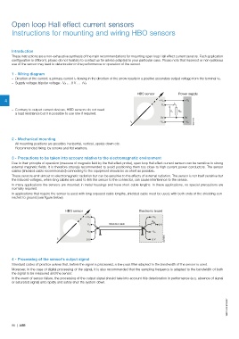
– Direction of the current: a primary current I P flowing in the direction of the arrow results in a positive secondary output voltage from the terminal V S.
– Supply voltage: bipolar voltage: -V A … 0 V … +V A
HBO sensor Power supply
4 + V A + V A
I s
V s
– Contrary to output current devices, HBO sensors do not need
V s R M
a load resistance but it is possible to use one if required.
0V 0V
G0217DG
I p - V A - V A
2 - Mechanical mounting
– All mounting positions are possible: horizontal, vertical, upside down etc.
– Recommended fixing: by screws and flat washers.
3 - Precautions to be taken into account relative to the electromagnetic environment
Due to their principle of operation (measure of magnetic field by the Hall effect probe), open loop Hall effect current sensors can be sensitive to strong
external magnetic fields. It is therefore strongly recommended to avoid positioning them too close to high current power conductors. The sensor
cables (shielded cable recommended) connecting to the equipment should be as short as possible.
These sensors emit almost no electromagnetic radiation but can be sensitive to the effects of external radiation. The sensor is not itself sensitive but
the induced voltages, when long cables are used to link the sensor to the connector, can cause interference to the sensor.
In many applications the sensors are mounted in metal housings and have short cable lengths. In these applications, no special precautions are
normally required.
In applications that require the sensor is used with long exposed cable lengths, shielded cable must be used, with both ends of the shielding con-
nected to ground (see figure below).
HBO sensor Electronic board
+ V A + V A
R M
Shielded cable
V s 0 V
- V A - V A
I p G0218DG
0 V 0 V
4 - Processing of the sensor's output signal
Standard codes of practice advise that, before the signal is processed, a low-pass filter adapted to the bandwidth of the sensor is used.
Moreover, in the case of digital processing of the signal, it is also recommended that the sampling frequency is adapted to the bandwidth of both
the signal to be measured and the sensor.
In the event of sensor failure, the processing of the output signal should take into account this deterioration in performance (e.g. absence of signal
or saturated signal) and rapidly and safely shut the system down.
1SBC140067S0201
96 | ABB