
Page 94 - Current & voltage sensors catalog
P. 94
Closed loop Hall effect current sensors
Instructions for mounting and wiring ES, MP, EL and CS sensors
Introduction
These instructions are a non-exhaustive synthesis of the main recommendations for mounting closed loop Hall effect current sensors.
Each application configuration is different, do not hesitate to contact us for advice adapted to your particular case.
Please note that incorrect or non-judicious use of the sensor may lead to deterioration in the performance or operation of the sensor.
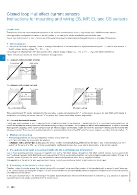
1 - Wiring diagram
– Direction of the current: A primary current I P flowing in the direction of the arrow results in a positive secondary output current Is from terminal M.
– Supply voltage: bipolar voltage -V A… 0 V … +V A
Closed loop Hall effect sensors can also operate with a unipolar supply voltage (-V A … 0 V or 0 V … +V A) under certain conditions.
Please contact your distributor for further details for this application.
4
1.1 - Sensors without screen terminal
Current sensor Power supply
+ + V A
I S R M
M 0 V
V M
– – V A
G0196DG
I P
1.2 - Sensors with screen terminal
Current sensor Power supply Current sensor Power supply
+ + V A + + V A
R M R M
I S I S
M 0 V M 0 V
V M V M
- - V A – – V A
I P E G0197DG I P E G0198DG
Recommended wiring Alternative wiring
The screen terminal "E" can be connected to the secondary negative terminal (marked "-") on the sensor. However the best EMC performance is
obtained by connecting the screen terminal "E" to ground by a copper braid strap as short as possible.
1.3 - Internal electrostatic screen
During very rapid variations in the primary conductor potential compared to the reference potential (high du/dt), a capacitive coupling effect can be
produced between the primary conductor and the secondary winding of the sensor. This coupling can lead to measurement errors. In order to eliminate
this capacitive coupling, some current sensors have an internal copper electrostatic screen between the secondary winding and the hole for the
primary conductor. This screen is linked internally either to an additional terminal marked "E", or to the sensor negative secondary terminal (marked "-").
2 - Mechanical mounting
– All mounting positions are possible: horizontal, vertical, upside down etc.
– Recommended fixing: by screws and flat washers.
– Installation with a primary bar: in this case, the sensor must be mechanically fixed, either only by the bar, or only by the enclosure, but never
by both at the same time (this type of fixing would lead to mechanical stresses that could lead to deterioration of the sensor casing).
3 - Precautions to be taken into account relative to the electromagnetic environment
Due to their operating principle (measure of magnetic field by the Hall effect probe), closed loop Hall effect current sensors can be sensitive to
strong external magnetic fields. It is therefore strongly recommended to avoid positioning them too close to high current power cables. The use of a
magnetic screen to protect the sensor may be advised for certain configurations with a strong magnetic influence.
The orientation of the sensor is also very important. Please contact your distributor for further information on this subject.
4 - Processing of the sensor's output signal
Standard codes of practice advise that, before the signal is processed, a low-pass filter adapted to the bandwidth of the sensor is used. Moreover,
in the case of digital processing of the signal, it is also recommended that the sampling frequency is adapted to the bandwidth of both the signal to
1SBC140066S0201 1SBC140066S0201
be measured and the sensor.
In the event of sensor failure, the processing of the output signal should take into account deterioration in performance (e.g. absence of signal or
saturated signal) and rapidly and safely shut the system down.
92 | ABB