
Page 99 - Current & voltage sensors catalog
P. 99
Electronic voltage sensors
Instructions for mounting and wiring VS sensors
Introduction
These instructions are a non-exhaustive synthesis of the main recommendations for mounting VS voltage sensors. Each application configuration is
different, do not hesitate to contact us for advice adapted to your particular case.
Please note that incorrect or non-judicious use of sensors may lead to deterioration in the performance or operation of the sensor.
Please refer to the mounting instructions ref. 1SBC147000M1702 (VS050 to VS1500) and ref. 1SBC146012M1701 (VS2000 to VS4200) for further
information.
1 - Wiring diagram
– Direction of the current: A positive primary differential voltage (U P = U HT+ - U HT- > 0) results in a positive secondary output current Is from terminal M.
– Supply voltage: bipolar voltage -V A …0 V …+V A
VS sensors can also operate with a unipolar supply voltage (-V A …0 V ou 0 V … +V A) under certain conditions.
4
Please contact your distributor for further details for this application.
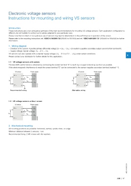
1.1 - VS voltage sensors with screen
The best EMC performance is obtained by connecting the screen terminal "E" to earth by a copper braid strap as short as possible.
If the electromagnetic interference is weak the screen terminal "E" can be connected to the sensor negative secondary terminal (marked "-").
VS sensor Power supply VS sensor Power supply
HT + + + V A HT + + + V A
R M R M
I S I S
M 0 V M 0 V
U P U P
V M V M
– – V A – – V A
G0191DG E G0192DG
HT – HT –
E
Recommended wiring Alternative wiring
1.2 - VS voltage sensors without screen
VS sensor Power supply
HT + + + V A
R M
I S
M 0 V
U P
V M
– – V A
G0193DG
HT –
2 - Mechanical mounting
All mounting positions are possible: horizontal, vertical, upside down, on edge.
Minimum distance between 2 sensors: 1 cm.
Recommended fixing: 2 M6 screws with flat washers.
1SBC140069S0201
ABB | 97