
Page 102 - EPR Catalog 2015
P. 102
Three-phase monitoring relays
Function diagrams
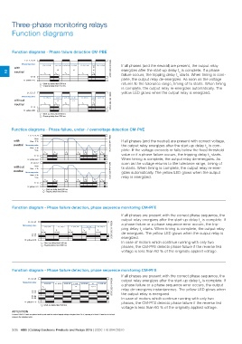
Function diagrams - Phase failure detection CM-PBE
L1, L2, L3, N 2CDC 252 045 F0203
Measuring value L1, L2, L3, N L1, L2, N L1, L2, L3, N L2, L3, N L1, L2, L3, N L1, L2 L1, L2, L3, N If all phases (and the neutral) are present, the output relay
with L3 energizes after the start-up delay ts is complete. If a phase
failure occurs, the tripping delay tv starts. When timing is com-
2 neutral L3 L1 N plete, the output relay de-energizes. As soon as the voltage
ts tv <ts ts <tv returns to the tolerance range, timing of ts starts. When timing
13-14 is complete, the output relay re-energizes automatically. The
R: yellow LED yellow LED glows when the output relay is energized.
ts = Start-up delay fixed 500 ms
tv = Tripping delay fixed 150 ms
L1, L2, L3 2CDC 252 046 F0203
Measuring value L1, L2, L3 L1, L2 L1, L2, L3 L1, L2 L1, L2, L3 L1, L2 L1, L2, L3
ts <ts L3 ts
without L3 L3
tv <tv
neutral
13-14
R: yellow LED
ts = Start-up delay fixed 500 ms
tv = Tripping delay fixed 150 ms
Function diagrams - Phase failure, under- / overvoltage detection CM-PVE
L1, L2, L3, N 2CDC 252 047 F0203
with Umax If all phases (and the neutral) are present with correct voltage,
Umax - 5 %
the output relay energizes after the start-up delay ts is com-
neutral Measuring value plete. If the voltage exceeds or falls below the fixed threshold
Umin + 5 % value or if a phase failure occurs, the tripping delay tv starts.
Umin When timing is complete, the output relay de-energizes. As
ts tv <ts ts <tv tv ts soon as the voltage returns to the tolerance range, timing of
13-14 ts starts. When timing is complete, the output relay re-ener-
R: yellow LED gizes automatically. The yellow LED glows when the output
L1, L2, L3 2CDC 252 048 F0203 relay is energized.
without Umax
Umax - 5 %
neutral Measuring value
Umin + 5 %
Umin
ts tv <ts ts <tv tv ts
13-14
R: yellow LED
ts = Start-up delay fixed 500 ms
tv = Tripping delay fixed 500 ms
Function diagram - Phase failure detection, phase sequence monitoring CM-PFE
L1, L2, L3 L1, L2, L3 L1, L3, L2 L1, L2, L3 L1, L2 L1, L2, L3 2CDC 252 061 F0208 If all phases are present with the correct phase sequence, the
Measuring value ts tv ts tv L3 ts
output relay energizes after the start-up delay ts is complete. If
11-14 a phase failure or a phase sequence error occurs, the trip-
11-12
R: yellow LED ping delay tv starts. When timing is complete, the output relay
de-energizes. The yellow LED glows when the output relay is
ts = Start-up delay fixed 500 ms
tv = Tripping delay fixed 500 ms energized.
In case of motors which continue running with only two
phases, the CM-PFE detects phase failure if the reverse fed
voltage is less than 60 % of the originally applied voltage.
Function diagram - Phase failure detection, phase sequence monitoring CM-PFS
L1, L2, L3 L1, L2, L3 L1, L3, L2 L1, L2, L3 L1, L2 L1, L2, L3 L1 L1, L2, L3 2CDC 252 013 F0208 If all phases are present with the correct phase sequence, the
Measuring value ts L3 L2, L3 output relay energizes after the start-up delay ts is complete. If
a phase failure or a phase sequence error occurs, the output
11-14 relay de-energizes instantaneous. The yellow LED glows when
11-12 the output relay is energized.
21-24 In case of motors which continue running with only two
21-22 phases, the CM-PFS detects phase failure if the reverse fed
R: yellow LED voltage is less than 60 % of the originally applied voltage.
ts = start-up delay fixed 500 ms
ATTENTION
If several CM-PFS units are placed side by side and the control supply voltage is higher than 415 V, spacing of at least 10 mm has to be kept
between the individual units.
2/35 ABB | Catalog Electronic Products and Relays 2015 | 2CDC 110 004 C0210