Page 103 - EPR Catalog 2015
P. 103

Three-phase monitoring relays
Function diagrams

CM-PSS.xx, CM-PVS.xx, CM.PAS.xx, CM-MPS.xx, CM-MPN.xx                                                                              CM-MPS.11, CM-MPS.21, CM-MPS.23                                                                                                                                                                                            2
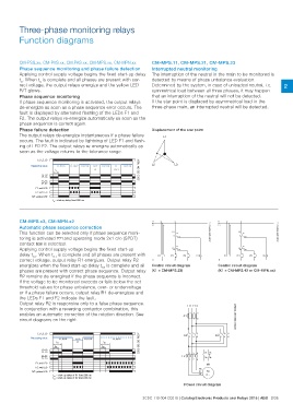
                                                                                                                                   Interrupted neutral monitoring
Phase sequence monitoring and phase failure detection                                                                              The interruption of the neutral in the main to be monitored is
Applying control supply voltage begins the fixed start-up delay                                                                    detected by means of phase unbalance evaluation.
tS. When tS is complete and all phases are present with cor-                                                                       Determined by the system, in case of unloaded neutral, i.e.
rect voltage, the output relays energize and the yellow LED                                                                        symmetrical load between all three phases, it may happen
R/T glows.                                                                                                                         that an interruption of the neutral will not be detected.
                                                                                                                                   If the star point is displaced by asymmetrical load in the
Phase sequence monitoring                                                                                                          three-phase main, an interrupted neutral will be detected.
If phase sequence monitoring is activated, the output relays
de-energize as soon as a phase sequence error occurs. The                                                                          Displacement of the star point
fault is displayed by alternated flashing of the LEDs F1 and
F2. The output relays re-energize automatically as soon as the
phase sequence is correct again.

Phase failure detection
The output relays de-energize instantaneous if a phase failure
occurs. The fault is indicated by lightning of LED F1 and flash-
ing of LED F2. The output relays re-energize automatically as
soon as the voltage returns to the tolerance range.

        L1, L2, L3      L1, L2, L3       L1, L3, L2 L1, L2, L3     L1, L2  L1, L2, L3    L1        L1, L2, L3  2CDC 252 094 F0207
Measuring value      ts                                              L3                L2, L3

              15-18
              15-16
              25-28
              25-26
      F1: red LED
      F2: red LED
R/T: yellow LED

                     ts = start-up delay fixed 200 ms

CM-MPS.x3, CM-MPN.x2                                                                                                               L1                                                                                                     L1
                                                                                                                                   L2                                                                                                     L2
Automatic phase sequence correction                                                                                                L3                                                                                                     L3
This function can be selected only if phase sequence moni-
toring is activated k and operating mode 2x1 c/o (SPDT)                                                                                                                     K1                                                                                                     K1
contact j is selected.                                                                                                                                                                              15                                                                                                     15
Applying control supply voltage begins the fixed start-up
delay tS1. When tS1 is complete and all phases are present with                                                                                                                            18                                                                                                     18
correct voltage, output relay R1 energizes. Output relay R2                                                                                                                                               16                                                                                                     16
energizes when the fixed start-up delay tS2 is complete and all                                                                                                                                                                   2CDC 253 008 F0014
phases are present with correct phase sequence. Output relay                                                                                                                                                                                                                                                                              2CDC 253 009 F0014
R2 remains de-energized if the phase sequence is incorrect.
If the voltage to be monitored exceeds or falls below the set                                                                                               25                                                                                                                         25
threshold values for phase unbalance, over- or undervoltage
or if a phase failure occurs, output relay R1 de-energizes and                                                                                    K1                                                                                                                         K1
the LEDs F1 and F2 indicate the fault.                                                                                                             28 26                                                                                                                      28 26
Output relay R2 is responsive only to a false phase sequence.
In conjunction with a reversing contactor combination, this                                                                                   K1              A1                                                          A1  H1                     K1                                  A1                                      A1  H1
enables an automatic correction of the rotation direction. See                                                                     N              K2                                                          K3                          N                                  K2                                      K3
circuit diagrams on the right.
                                                                                                                                                              A2                                                          A2                                                             A2                                      A2

                                                                                                                                   Control circuit diagram                                                                                Control circuit diagram
                                                                                                                                   (K1 = CM-MPS.23)                                                                                       (K1 = CM-MPS.43 or CM-MPN.xx)

                                                                                                                                                                                                                  L1 L2 L3                               2CDC 252 087 F0b07

                                                                                                                                                                                                                        135

                                                                                                                                                                                                              -F1

                                                                                                                                                                                                                        246

        L1, L2, L3                                                                                             2CDC 252 085 F0207                                                                                      135                         135
Measuring value
                                                                                                                                                                                                              -K2 2 4 6                   -K3 2 4 6
              15-18
              15-16          L1, L2, L3  L1, L2        L1, L2, L3                      L1, L3, L2
              25-28    tS1                 L3
              25-26  tS2                                                     tS1
      F1: red LED                                                          tS2
      F2: red LED
R/T: yellow LED                                                                                                                                                                                                          154      97 95
                                                                                                                                                                                                                                  98 96
                                                                                                                                                                                                              -F2

                                                                                                                                                                                                                         326

                                                                                                                                                                                                                                  -M1

                     tS1 = start-up delay of R1 fixed 250 ms                                                                                                                                                                      W1
                     tS2 = start-up delay of R2 fixed 200 ms
                                                                                                                                                                                                                                  V1 M

                                                                                                                                                                                                                                  U1 3 ~

                                                                                                                                                                                                              Power circuit diagram

                                                                                                                                   2CDC 110 004 C0210 | Catalog Electronic Products and Relays 2015 | ABB 2/36
   98   99   100   101   102   103   104   105   106   107   108