
Page 105 - EPR Catalog 2015
P. 105
Three-phase monitoring relays
Function diagrams
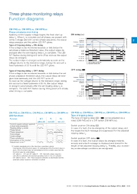
CM-PAS.xx, CM-MPS.xx, CM-MPN.xx ON-delay A
Phase unbalance monitoring L1, L2, L3 L3 2CDC 252 092 F0207 2
Applying control supply voltage begins the fixed start-up Unbalance L1, L2, L3 L1, L2
delay tS. When tS is complete and all phases are present with Unbalance - Hysteresis ts tv <tv tv
correct voltage and with correct phase sequence, the output <tv <tv
relays energize and the yellow LED R/T glows. Measuring value ts = start-up delay fixed 200 ms
Unbalance + Hysteresis tv = adjustable tripping delay
Type of tripping delay = ON-delay
If the voltage to be monitored exceeds or falls below the Unbalance
set phase unbalance threshold value, the output relays de-
energize after the set tripping delay tV is complete. The LED 15-18
R/T flashes during timing and turns off as soon as the output 15-16
relays de-energize. 25-28
The output relays re-energize automatically as soon as the 25-26
voltage returns to the tolerance range, taking into account a
fixed hysteresis of 20 % and the LED R/T glows. F1: red LED
F2: red LED
R/T: yellow LED
Type of tripping delay = OFF-delay OFF-delay B
If the voltage to be monitored exceeds or falls below the set
phase unbalance threshold value, the output relays de-ener- L1, L2, L3 L3 tv 2CDC 252 093 F0207
gize instantaneously and the LED R/T turns off. Unbalance L1, L2, L3 L1, L2
As soon as the voltage returns to the tolerance range, taking Unbalance - Hysteresis ts
into account a fixed hysteresis of 20 %, the output relays
re-energize automatically after the set tripping delay tV is Measuring value
complete. The LED R/T flashes during timing and turns steady Unbalance + Hysteresis
when timing is complete.
Unbalance
15-18
15-16
25-28
25-26
F1: red LED
F2: red LED
R/T: yellow LED
ts = start-up delay fixed 200 ms
tv = adjustable tripping delay
CM-PSS.xx, CM-PSV.xx, CM-PAS.xx, CM-MPS.xx, CM-MPN.xx CM-PSS.xx, CM-PSV.xx, CM-PAS.xx, CM-MPS.xx, CM-MPN.xx
LED functions Type of tripping delay
The type of tripping delay A / B can be adjusted via a
Function R/T: F1: F2: rotary (CM-PxS.xx) or a DIP switch (CM-MPx.xx).
Control supply voltage applied, yellow LED red LED red LED Switch position ON-delay A:
output relay energized In case of a fault, the de-energizing of the output relays and
Tripping delay tV active V -- the respective fault message are suppressed for the adjusted
Phase failure tripping delay tV.
Phase sequence W --
Overvoltage - VW Switch position OFF-delay B:
Undervoltage - W alternating In case of a fault, the output relays de-energize instanta-
Phase unbalance - V- neously and a fault message is displayed and stored for the
Interruption of the neutral - -V length of the adjusted tripping delay tV. Thereby, also momen-
Adjustment error 1) - VV tary undervoltage conditions are recognized.
- VW
W WW
1) Possible misadjustments of the front-face operating controls:
Overlapping of the threshold values: An overlapping of the threshold values is
given, if the threshold value for overvoltage is set to a smaller value than the
threshold value for undervoltage.
DIP switch 3 = OFF and DIP switch 4 = ON: Automatic phase sequence
correction is activated and selected operating mode is 1x2 c/o contacts
DIP switch 2 and 4 = ON: Phase sequence detection is deactivated and the
automatic phase sequence correction is actived
2CDC 110 004 C0210 | Catalog Electronic Products and Relays 2015 | ABB 2/38