
Page 104 - EPR Catalog 2015
P. 104
Three-phase monitoring relays
Function diagrams
CM-PSS.xx1), CM-PVS.xx2), CM-MPS.xx2), CM-MPN.xx2)
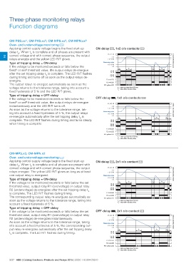
Over- and undervoltage monitoring j
Applying control supply voltage begins the fixed start-up ON-delay A, 1x2 c/o contacts j 2CDC 252 090 F0207
delay tS. When tS is complete and all phases are present with L1, L2, L3
>U
2 correct voltage and with correct phase sequence, the output
>U-5%
relays energize and the yellow LED R/T glows.
Type of tripping delay = ON-delay Measuring value ts tv <tv tv
If the voltage to be monitored exceeds or falls below the <U+5% ts = start-up delay fixed 200 ms <tv <tv
fixed1) or set2) threshold value, the output relays de-energize <U tv = adjustable tripping delay
after the set tripping delay tV is complete. The LED R/T flashes
during timing and turns off as soon as the output relays de- 15-18
energize. 15-16
The output relays re-energize automatically as soon as the 25-28
voltage returns to the tolerance range, taking into account a 25-26
fixed hysteresis of 5 % and the LED R/T glows.
F1: red LED
F2: red LED
R/T: yellow LED
Type of tripping delay = OFF-delay OFF-delay B, 1x2 c/o contacts j
If the voltage to be monitored exceeds or falls below the
fixed1) or set2) threshold value, the output relays de-energize L1, L2, L3 2CDC 252 091 F0207
instantaneously and the LED R/T turns off. >U
As soon as the voltage returns to the tolerance range, tak- ts tv
ing into account a fixed hysteresis of 5 %, the output relays >U-5%
re-energize automatically after the set tripping delay tV is
complete. The LED R/T flashes during timing and turns steady Measuring value
when timing is complete. <U+5%
<U
15-18
15-16
25-28
25-26
F1: red LED
F2: red LED
R/T: yellow LED
ts = start-up delay fixed 200 ms
tv = adjustable tripping delay
CM-MPS.x3, CM-MPN.x2 ON-delay A, 2x1 c/o contact i
Over- and undervoltage monitoring i L1, L2, L3 2CDC 252 006 F0207
Applying control supply voltage begins the fixed start-up >U
delay tS. When tS is complete and all phases are present with ts tv <tv tv
correct voltage and with correct phase sequence, the output >U-5% ts = start-up delay fixed 200 ms <tv <tv
relays energize. The yellow LED R/T glows as long as at least tv = adjustable tripping delay
one output relay is energized. Measuring value
<U+5%
Type of tripping delay = ON-delay <U
If the voltage to be monitored exceeds or falls below the set
threshold value, output relay R1 (overvoltage) or output relay 15-18
R2 (undervoltage) de-energizes after the set tripping delay tV 15-16
is complete. The LED R/T flashes during timing. 25-28
The corresponding output relay re-energizes automatically as 25-26
soon as the voltage returns to the tolerance range, taking into
account a fixed hysteresis of 5 %. F1: red LED
F2: red LED
Type of tripping delay = OFF-delay R/T: yellow LED
If the voltage to be monitored exceeds or falls below the set
threshold value, output relay R1 (overvoltage) or output relay OFF-delay B, 2x1 c/o contact i
R2 (undervoltage) de-energizes instantaneously.
As soon as the voltage returns to the tolerance range, taking L1, L2, L3 2CDC 252 007 F0207
into account a fixed hysteresis of 5 %, the corresponding out- >U
put relay re-energizes automatically after the set tripping delay ts tv
tV is complete. The LED R/T flashes during timing. >U-5% ts = start-up delay fixed 200 ms
tv = adjustable tripping delay
Measuring value
<U+5%
<U
15-18
15-16
25-28
25-26
F1: red LED
F2: red LED
R/T: yellow LED
2/37 ABB | Catalog Electronic Products and Relays 2015 | 2CDC 110 004 C0210