Page 110 - EPR Catalog 2015
P. 110

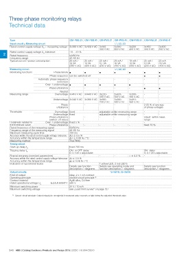
Three-phase monitoring relays
Technical data

Type                                                        CM-PSS.31 CM-PSS.41 CM-PVS.31 CM-PVS.41 CM-PVS.81 CM-PAS.31 CM-PAS.41

Input circuit = Measuring circuit                                                                                             L1, L2, L3

Rated control supply voltage US = measuring voltage 3x380 V AC 3x400 V AC 3x160-                                              3x300-      3x200-    3x160-    3x300-
                                                                                                                    300 V AC  500 V AC    400 V AC  300 V AC  500 V AC

2 Rated control supply voltage US tolerance                 -15...+10 %
        Rated frequency                                     50/60 Hz

Frequency range                                             45-65 Hz

Typical current / power consumption                         25 mA /      25 mA /     25 mA /                                  25 mA /     19 mA /   25 mA /   25 mA

                                                            18 VA        18 VA       10  VA                                   18 VA       10 VA     10 VA     /18 VA

                                                            (380 V AC) (400 V AC) (230 V AC) (400 V AC) (300 V AC) (230 V AC) (400 V AC)

Measuring circuit                                                                                                       L1, L2, L3
Monitoring functions                     Phase failure ½ ½ ½ ½ ½ ½ ½

                                     Phase sequence can be switched off                                                                             ½½

                       Automatic phase sequence - - - - - -                                                                                                   -
                                                                                                                                                              -
                                               correction
                                Over- / undervoltage ½ ½ ½ ½ ½ -

                                   Phase unbalance - - - - - ½ ½

Measuring range                                Neutral -                 -           -                                        -           -         --
                                        Overvoltage 3x418 V AC           3x440 V AC  3x220-                                   3x420-      3x300-    --
                                                                                     300 V AC                                 500 V AC    400 V AC
                                       Undervoltage 3x342 V AC           3x360 V AC                                                                 --
                                                                                     3x160-                                   3x300-      3x210-
                                                 Phase -                 -           230 V AC                                 380 V AC    300 V AC  2-25 % of average
                                           unbalance                                                                                                of phase voltages
                                                                                     -                                        -           -

Thresholds                               Overvoltage fixed                           adjustable within measuring range                              --
                                                                                     adjustable within measuring range                              --
                                       Undervoltage fixed                            ---                                                            adjust. within meas.
                                                                                                                                                    range
                                   Phase unbalance -                     -           ---                                                            -
                                                                                                                                                    fixed 20 %
                                   (switch-off value)
                                                                                                                                                    ON- delay
Hysteresis related to              Over- / undervoltage fixed 5 %                                                                                   0; 0.1-30 s adjustable
                                                                                                                                                    --
the threshold value                Phase unbalance -                     -
                                                                                                                                                    Details see function
Rated frequency of the measuring signal                     50/60 Hz                                                                                description / -diagrams

Frequency range of the measuring signal                     45-65 Hz

Maximum measuring cycle time                                100 ms

Accuracy within the rated control supply voltage tolerance ͬU ͨ 0.5 %

Accuracy within the temperature range                       ͬU ͨ 0.06 % / °C

Measuring method                                            True RMS

Timing circuit

Start-up delay tS                                           fixed 200 ms             - - < Ȁ 0.2 %
Tripping delay tV
                                                            ON- or OFF-delay         1 yellow LED, 2 red LED's
Repeat accuracy (constant parameters)                       0; 0.1-30 s adjustable   Details see operating mode and
Accuracy within the rated control supply voltage tolerance  --                       function description / -diagrams
Accuracy within the temperature range                       ͬt ͨ 0.5 %
Indication of operational states                            ͬt ͨ 0.06 % / °C

                                                            Details see function
                                                            description / -diagrams

Output circuits                                                                                                               15-16/18, 25-26/28

Kind of output                                               relay, 2 x 1 c/o contact
Operating principle                                          closed-circuit principle 1)
Contact material                                             AgNi alloy, Cd free
Rated operational voltage Ue         IEC/EN 60947-1 250 V

Minimum switching power                                      24 V / 10 mA
Maximum switching voltage                                    see „Load limit curves“ on page 127

1) Closed-circuit principle: Output relay(s) de-energize(s) if measured value exceeds or falls below the adjusted threshold value

2/43 ABB | Catalog Electronic Products and Relays 2015 | 2CDC 110 004 C0210
   105   106   107   108   109   110   111   112   113   114   115