
Page 282 - EPR Catalog 2015
P. 282
Analog signal converters
Overview
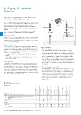
Applications for analog signal processing and correct 0-10 V 0-10 V
solution using CC-E and CC-U converters Controller
e.g. AC500
Nearly every process includes a control system that receives
data by means of analog signals and then evaluates the data 1. 2.
and sets the respective parameters correspondingly. Analog signal converter Analog signal converter
When transmitting analog signals numerous problems may
arise which can disturb or even block an ideal behavior of the (e.g. CC-E or CC-U) (e.g. CC-E or CC-U)
process.
Below we have listed some processing problems together 100 m 0-20 mA 100 m 4-20 mA
with the respective solutions to solve these problems: Actuator
4 Measuring sensor
Signal conversion 2CDC 282 013 F0206
Sometimes the available signals cannot be processed by the
controller or the actuator. In this case, signal converters are
required to convert the input signal (or different input signals)
to the desired output signal.
Signal amplification Signal separation
If long lines or high burdens have to be operated, it may be – Protection against overvoltage
necessary to amplify the signal. CC analog signal converters
require only low input power and provide high output power. The increased use of micro-electronics make controls
Thus, there are no restrictions for the converter's position on much more sensitive against overvoltages, resulting from
the line, i.e. it can be used lightning discharges or switching processes. Suppression
– for signal refreshing (1) at the end of the line (low input diodes are incorporated in the input of the CC analog
signal converters which enable the converters to arrest
power) overvoltages with low energy level (resulting from switch-
– or for signal amplification (2) at the beginning of the line ing processes) by themselves. The products furthermore
provide electrical isolation between input, output and
(high output power). supply circuit for protection of the controller connected to
the output.
Signal filtering
Particularly on long lines or in rough industrial environments – Protection against ground loops
the signals are exposed to high electromagnetic interferenc- If components are used which refer to ground, the mea-
es. The frequency of the coupled interference signals may be suring signals can be falsified by a so-called ground loop.
in the range of the common mains frequency (50 Hz) or even In this case, certain parts of the signal are transmitted
much higher (in case of frequency converters). According to via earth and not via the analog transmission line, thus
the specific requirements, analog signal converters are avail- causing incorrect evaluation of the signal. The electrical
able which provide reliable suppression of those interferences isolation between the input and the output disconnects
by means of an input low-pass filter. these ground loops and thus enables correct signal
transmission.
½ existing
̆ existing for some devices
˽ pending
Approvals CC-E/STD
CC-E I/I
A UL 508, CAN/CSA C22.2 No.14 CC-U/STD
CC-U/STDR
CC-E/RTD
CC-U/RTD
CC-E / TC
CC-U/ TC
CC-U/ TCR
CC-E/I
CC-E IAC/ILPO
CC-U/I
CC-U/V
½½½½½½½½½½½½½
A UL 1604 (Class I, Div 2, hazardous locations), ̆ ½ ̆ ½ ̆ ½ ̆ ½ ½
CAN/CSA C22.2 No.213
K CB scheme ½½
E CCC ½½
Marks
a CE ½½½½½½½½½½½½½
b C-Tick ½½½½½½½½½½½½½
4/3 ABB | Catalog Electronic Products and Relays 2015 | 2CDC 110 004 C0210