
Page 277 - EPR Catalog 2015
P. 277
Electronic protection devices EPD24
Technical information
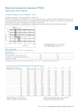
Time/Current characteristic curve (Tambient = 25 °C)
The trip time is typically 3 s in the range between 1.1 and 1.8 x I 1)
N.
Electronic current limitation occurs at typically 1.8 x IN1) which means that under all overload conditions (independent of the power sup-
ply and the resistance of the load circuit) the max. overload before disconnection will not exceed 1.8 x IN1) times the current rating. Trip
time is between 100 ms and 3 sec (depending on overload or at short circuit).
Without this current limitation a considerably higher overload current would flow in the event of an overload or short circuit.
disconnection 3
typically 1.1 x IN 1.8 x IN1)
10000
1000
trip time in seconds 100
current limitation 1)
typically 1.8 x IN
10
5
1
0. 1
0.01 1 23 4 5 IK 1) Current limitation typically 1.8 x IN at IN = 0.5 A...6 A
0 Current limitation typically 1.5 x IN at IN = 8 A or 10 A
Current limitation typically 1.3 x IN at IN = 12 A
...times rated current
Maximum cable lenghts 3 6
EPD24 reliably trips from 0 Ω up to max. circuit resistance Rmax. 19.2 19.2
Calculation of Rmax 3.75 7.50
5.07 2.51
Selected rating IN (A)
Operating voltage US (V DC) (= 80 % of 24 V) 2)
Trip current Iab = 1.25 x IN (A) (EPD24 trips after 3 s)
Rmax (Ω) = (UB/Iab) -0.050
2) Voltage drop of EPD24 and tolerance of trip point (typically 1.1 x IN = 1.05 ... 1.35 x IN) have been taken into account
Selection table for the incoming cable lengths with different cable cross-sections
Cable cross section A (mm2) 0.14 0.25 0.34 0.5 0.75 1.00 1.50
Cable length L (m) (= single length)
cable resistance (Ω) = (U0 x 2 x L) / A 3) 0.36 0.24 0.18 0.12
5 1.27 0.71 0.52 0.71 0.47 0.36 0.24
10 1.07 0.71 0.53 0.36
15 2.54 1.42 1.05 1.42 0.95 0.71 0.47
20 1.78 1.19 0.89 0.59
25 3.81 2.14 1.57 2.14 1.42 1.07 0.71
30 2.49 1.66 1.25 0.83
35 5.09 2.85 2.09 2.85 1.90 1.42 0.95
40 3.20 2.14 1.60 1.07
45 6.36 3.56 2.62 3.56 2.37 1.78 1.19
50 5.34 3.56 2.67 1.78
75 7.63 4.27 3.14 7.12 4.75 3.56 2.37
100 8.90 5.93 4.45 2.97
125 8.90 4.98 3.66 10.68 7.12 5.34 3.56
150 12.46 8.31 6.23 4.15
175 10.17 5.70 4.19 14.24 9.49 7.12 4.75
200 16.02 10.68 8.01 5.34
225 11.44 6.41 4.71 17.80 11.87 8.90 5.93
250
12.71 7.12 5.24
19.07 10.68 7.85
25.34 14.24 10.47
31.79 17.80 13.09
38.14 21.36 15.71
44.50 24.92 18.32
50.86 28.48 20.94
57.21 32.04 23.56
63.57 35.60 26.18
3) Resistivity of copper U = 0.0178 (Ω x mm2)/m Example 3: mixed wiring: (Control cabinet --- sensor/actuator level)
Example 1: max. length for 1.5 mm2 and 3 A: 214 m R1 = 40 m for 1.5 mm2 and R2 = 5 m for 0.25 mm2:
Example 2: max. length for 1.5 mm2 and 6 A: 106 m R1 = 0.95 Ω, R2 = 0.71 Ω, total (R1 + R2) = 1.66 Ω
2CDC 110 004 C0210 | Catalog Electronic Products and Relays 2015 | ABB 3/78