
Page 279 - EPR Catalog 2015
P. 279
Electronic protection devices EPD24 3
Installation guidelines
The EPD24 features an integral power distribution system.
The following wiring modes are possible with various pluggable current and signal busbars:
– LINE+ (24 V DC)
– 0V
Caution: The electronic devices EPD24 require a 0 V connection
– Auxiliary contacts
LINE+ busbar continuous busbar (12.5 x n)-3 = length of busbars ± 0.5
2CDE605100R0500 500 mm length, cut e. g. (12.5 x 5)-3 = 59.5 ± 0.5
signal bar
2CDE605200R0021
remove protection against 0 V busbar insert protection against
brush contact from bottom side 2CDE605100R0500 brush contact
insert busbars 12.5 x n = width of protector block
and protection slides e. g. 12.5 x 5 = 62.5
to be flush with housing sides
insert signal
bars to be flush with
housing and place them
centrally over the contacts
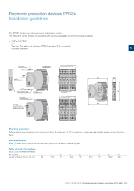
Mounting procedure
Before wiring insert busbars into protector block. A maximum of 10 connection cycles are permissible using connecting bus-
bars.
Recommendation
After 10 units the busbars should be interrupted and receive a new entry live.
Table of length for busbars 2 3 4 5 6 7 8 9 10
22 34.5 47 59.5 72 84.5 97 109.5 122
(Order code 2CDE605100R0500)
No. of units
Length of busbar (mm) ± 0.5 mm
2CDC 110 004 C0210 | Catalog Electronic Products and Relays 2015 | ABB 3/80