
Page 276 - EPR Catalog 2015
P. 276
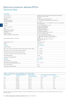
Electronic protection devices EPD24
Technical data

        General data                                                                 backup fuse for EPD24 not required because of the integral
                                                                                     redundant fail-safe element
        Fail-Safe element                                                            moulded
        Housing material                                                             symmetrical rail to EN 50022-35x7.5
        Mounting                                                                     0...+50 °C (without condensation, see EN 60204-1)
        Ambient temperature                                                          -20...+70 °C
        Storage temperature                                                          96 hrs/95 % RH/40 °C to IEC 60068-2-78, test Cab. climate class
        Humidity                                                                     3K3 to EN 60721
                                                                                     3 g, test to IEC 60068-2-6 test Fc
3 Vibration                                                                          housing: IP20 DIN 40050
                                                                                     terminals: IP20 DIN 40050
        Degree of protection                                                         emission: EN 61000-6-3
        EMC                                                                          susceptibility: EN 61000-6-2
        (EMC directive, CE logo)                                                     0.5 kV/pollution degree 2
        Isolations coordination                                                      reinforced insulation in operating area
        (IEC 60934)                                                                  max. 32 V DC (load circuit)
        Dielectric strength                                                          n/a, only electronic disconnection
        Isolation resistance (OFF condition)                                         UL 2367 Solid State Overcurrent Protectors
                                                                                     UL 1604, (class I, division 2, groups A, B, C, D)
        Approvals/Declarations of conformity                                         UL 508
                                                                                     CSA C22.2 No. 213 (class I, division 2)
        Dimensions (B x H x T)                                                       CSA C22.2 No. 142
        Weight                                                                       CE logo
        Terminals                                                                    12.5 x 80 x 83 mm
        Screw terminals
        Max. cable cross section flexible with wire end ferrule w/wo plastic sleeve  approx. 65 g
        Multi-lead connection (2 identical cables) rigid/flexible
        Flexible with wire end ferrule without plastic sleeve                        Line+/LOAD+/0V
        Flexible with TWIN wire end ferrule with plastic sleeve
        Wire stripping length                                                        M4
        Tightening torque (EN 60934)
        Terminals                                                                    0.5 – 10 mm2
        Screw terminals
        Max. cable cross section flexible                                            0.5 – 4 mm2
        with wire end ferrule w/wo plastic sleeve
        Wire stripping length                                                        0.5 – 2.5 mm2
        Tightening torque (EN 60934)
                                                                                     0.5 – 6 mm2

                                                                                     10 mm

                                                                                     1.5 – 1.8 Nm

                                                                                     aux. contacts

                                                                                     M3

                                                                                     0.25 - 2.5 mm2

                                                                                     8 mm

                                                                                     0.5 Nm

Table 1: voltage drop, current limitation, max. load current

current rating  typically voltage drop  active current                               max. load current at 100 % ON duty

IN              UON at IN               limitation (typically)                       Tambient = 40 °C  Tambient = 40 °C

0.5 A           70 mV                   1.8 x IN                                     0.5 A             0.5 A
1A              80 mV                   1.8 x IN
2A              130 mV                  1.8 x IN                                     1A 1A
3A              80 mV                   1.8 x IN
4A              100 mV                  1.8 x IN                                     2A 2A
6A              130 mV                  1.8 x IN
8A              120 mV                  1.5 x IN                                     3A 3A
10 A            150 mV                  1.5 x IN
12 A            180 mV                  1.3 x IN                                     4A 4A

                                                                                     6A 5A

                                                                                     8A 7A

                                                                                     10 A              9A

                                                                                     12 A              10.8 A

Attention: when mounted side-by-side without convection the ERD24 should not carry more than 80 % of its rated load with 100 % ON duty due
to thermal effects.

3/77 ABB | Catalog Electronic Products and Relays 2015 | 2CDC 110 004 C0210