
Page 297 - EPR Catalog 2015
P. 297
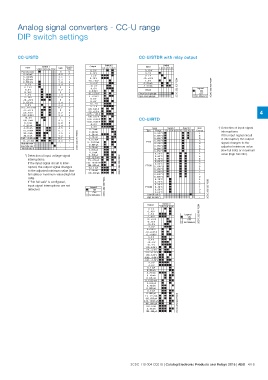
Analog signal converters - CC-U range
DIP switch settings
CC-U/STD CC-U/STDR with relay output
Input Switch 1 Gain Coarse Output Switch 2 Input Switch
12345 678 Type 123456 123456
0 0...10 V
Potentiometer A...D 0 0...5 V 0...5 V
4...5 C 0...1 V
0...50 mV 0...1 5 0...10 V -10...+10 V
7...9 1 1...5 V
0...100 mV 3...4 8 1...5 V 0...20 mA
3 4...20 mA
0...250 mV 0 0 2...10 V 2CDC 282 005 F0204
5...7 6 2CDC 282 003 F0204
0...500 mV 2 -10...+10 V
2 8
0...1 V 7...9 3 -5...+5 V
2...4 0
0...2.5 V 3 -10...0 V
0 3
0...5 V 3...4 D -5...0 V Output Legend
3...4 0 ON
0...10 V B...F 6 0...6.66 V OFF
4
1...5 V 0 2 -10...+3.33 V Closed-circuit principle no influence
5...7 5 Open-circuit principle
2... 10 V 3...4 B -5...+1.66 V
3
-10...+10 V 2 4 0...8 V
4...5 1
0...125 mV A...D 4 0...4 V
2...4 3
0...8 V 4...5 D -10...-2 V
0...1 5
-22.5...+22.5 mV 4...5 - -5...-1 V
4...2 -
-11...+11 V B...F - 1.25...6.25 V
4...6
2.5...7.5 V -7.5...+2.5 V 4
-
3.33...9.99 V - -3.75...+1.25 V *) Detection of input signal
- interruptions:
10...0 V 1.66...8.33 V CC-U/RTD If the input signal circuit
is interrupted, the output
100...0 mV -6.66...+6.66 V signal changes to the
adjusted minimum value
0...1 mA -3.33...+3.33 V (low fail safe) or maximum
value (high fail safe).
0...20 mA -8...0 V
4...20 mA -4...0 V Input Switch 1 Switch 2 Gain
Coarse
10...50 mA 0...1 mA Type Range 1 2 3 4 5 6 1 2 3 4 5 6
2CDC 282 019 F0203 F
20...4 mA 2CDC 282 003 F02040...20 mA 0...500 °C E
D
20...0 mA 2CDC 282 020 F02034...20 mA 0...550 °C C
B
-0.45...+0.45 mA 0...10 mA 0...600 °C A
9
-55...+55 mA 0...0.5 mA PT10 0...650 °C 8
0...700 °C F
High fail safe *) 0...13.33 mA E
B
Low faile safe *) 0...666 μA 0...750 °C A
9
No fail safe *) 0...16 mA 0...800 °C 8
3
0...800 μA 0...850 °C 2
1
0...8 mA 0...50 °C 0
8
*) Detection of input voltage signal 0...400 μA 0...60 °C 3
interruptions: 2
If the input signal circuit is inter- 2.5...12.5 mA 0...70 °C 1
rupted, the output signal changes 0
to the adjusted minimum value (low 125...625 μA 0...80 °C 0
fail safe) or maximum value (high fail -
safe). 3.33...16.66 mA 0...90 °C -
If "No fail safe" is configured, PT100 0...100 °C
input signal interruptions are not 166...833 μA
detected.
0.2...1 mA 0...200 °C
2...10 mA 0...300 °C
100...500 μA 0...400 °C
0...500 °C
0...10 °C 2CDC 282 003 F0204
2CDC 282 023 F0203
0...20 °C
0...30 °C
Legend PT1000 0...40 °C
ON
OFF 0...50 °C
no influence 0...60 °C
Low fail safe *)
High fail safe *)
Output Switch 3
123456
0...5 V
0...10 V
1...5 V Legend
ON
2...10 V OFF
-10...+10 V no influence
-5...+5 V
-10...0 V
-5...0 V
0...6.66 V
-10...+3.33 V
-5...+1.66 V
0...8 V
0...4 V
-10...-2 V
-5...-1 V
1.25...6.25 V
-7.5...+2.5 V
-3.75...+1.25 V
1.66...8.33 V
-6.66...+6.66 V
-3.33...+3.33 V
-8...0 V
-4...0 V
0...1 mA
0...20 mA
4...20 mA
0...10 mA
0...0.5 mA
0...13.33 mA
0...666 μA
0...16 mA
0...800 μA
0...8 mA
0...400 μA 2CDC 282 024 F0203
2.5...12.5 mA
125...625 μA
3.33...16.66 mA
166...833 μA
0.2...1 mA
2...10 mA
100...500 μA
2CDC 110 004 C0210 | Catalog Electronic Products and Relays 2015 | ABB 4/18