
Page 52 - EPR Catalog 2015
P. 52
CT-S range
Function diagrams
Remarks Terminal designations on the device and in the diagrams:
The 1st c/o contact is always designated 15-16/18.
1 Legend The 2nd c/o contact is designated 25-26/28, if it responds to
the time delay.
G Control supply voltage not applied / Output contact open If the 2nd c/o contact is selected as an instantaneous con-
B Control supply voltage applied / Output contact closed tact, the designation 25-26/28 is replaced by 21-22/24.
Control supply voltage is always applied to terminals A1-A2.
A1-Y1/B1 Control input with voltage-related triggering
Y1-Z2 Control input with volt-free triggering Function of the yellow LEDs:
X1-Z2 Control input with volt-free triggering On devices without the function ‘2nd c/o contact selectable
as instantaneous contact’, the yellow LED R glows as soon as
Remote potentiometer connection: the output relay energizes and turns off when the output relay
When an external potentiometer is connected to the remote de-energizes.
potentiometer connection (terminals Z1-Z2, Z3-Z2 respective-
ly), the internal, front-face potentiometer is disabled and the Devices with the function ‘2nd c/o contact selectable as
time adjustment is made via the external potentiometer. instantaneous contact’ have two yellow LEDs, designated R1
and R2. LED R1 shows the status of the 1st c/o contact (15-
2nd c/o contact selectable as instantaneous contact: 16/18) and LED R2 shows the status of the 2nd c/o contact
When switch position Inst. “I” is selected, the functionality of (25-26/28, 21-22/24 resp.). LED R1 or R2 glow as soon as
the 2nd c/o contact changes to an instantaneous contact. the corresponding output relay energizes and turns off when
It acts like the c/o contacts of a switching relay, i.e. apply- the corresponding output relay de-energizes.
ing or interrupting the control supply voltage energizes or
de-energizes the c/o contact. The designation of the 2nd c/o
contact changes from 25-26/28 to 21-22/24, when selected
as instantaneous contact.
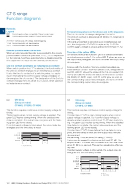
A ON-delay A ON-delay
(Delay on make)
CT-MVS, CT-ERS, CT-WBS (Delay on make)
This function requires continuous control supply voltage for CT-MFS, CT-MBS
timing.
Timing begins when control supply voltage is applied. The This function requires continuous control supply voltage for
green LED flashes during timing. When the selected time timing.
delay is complete, the output relay energizes and the flash- If control input Y1-Z2 is open, timing begins when control
ing green LED turns steady. supply voltage is applied. Or, if control supply voltage is
If control supply voltage is interrupted, the output relay de- already applied, opening control input Y1-Z2 also starts tim-
energizes and the time delay is reset. ing. The green LED flashes during timing. When the selected
time delay is complete, the output relay energizes and the
flashing green LED turns steady.
If control input Y1-Z2 closes before the time delay is com-
plete, the time delay is reset and the output relay remains
de-energized.
Pause timing / Accumulative ON-delay (CT-MFS):
Timing can be paused by closing control input X1-Z2. The
elapsed time t1 is stored and continues from this time value
when X1-Z2 is re-opened. This can be repeated as often as
required.
If control supply voltage is interrupted, the output relay de-
energizes and the time delay is reset.
A1-A2 2CDC 252 017 F0206
15-18, 25-28 2CDC 252 018 F0206
15-16, 25-26
21-24
21-22
green LED
t <t
t = adjusted time delay
A1-A2
Y1-Z2
15-18, 25-28
15-16, 25-26
21-24
21-22
X1-Z2
green LED
t t1 t3 t2
t = adjusted time delay t1 + t2 = t
t3 = pause timing
1/41 ABB | Catalog Electronic Products and Relays 2015 | 2CDC 110 004 C0210