
Page 55 - EPR Catalog 2015
P. 55
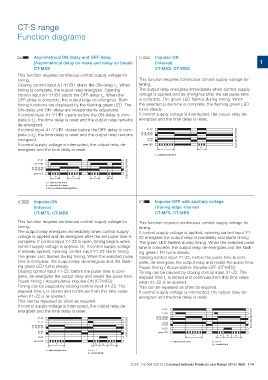
CT-S range
Function diagrams

AB  Asymmetrical ON-delay and OFF-delay                                        CA              Impulse-ON
    (Asymmetrical delay on make and delay on break)                                            (Interval)
    CT-MXS                                                                                     CT-MVS, CT-WBS                                                                                                                                                                                1

This function requires continuous control supply voltage for                   This function requires continuous control supply voltage for
                                                                               timing.
timing.                                                                        The output relay energizes immediately when control supply
                                                                               voltage is applied and de-energizes after the set pulse time
Closing control input A1-Y1/B1 starts the ON-delay t1. When                    is complete. The green LED flashes during timing. When
timing is complete, the output relay energizes. Opening                        the selected pulse time is complete, the flashing green LED
                                                                               turns steady.
control input A1-Y1/B1 starts the OFF-delay t2. When the                       If control supply voltage is interrupted, the output relay de-
OFF-delay is complete, the output relay de-energizes. Both                     energizes and the time delay is reset.

timing functions are displayed by the flashing green LED. The                  2CDC 252 038 F0206A1-A2
                                                                                                                                                                                                                                                  2CDC 252 024 F020615-18, 25-28
ON-delay and OFF-delay are independently adjustable.                           15-16, 25-26

If control input A1-Y1/B1 opens before the ON-delay is com-                             21-24
                                                                                        21-22
plete (<t1), the time delay is reset and the output relay remains                 green LED
de-energized.
                                                                                               t                                           <t
If control input A1-Y1/B1 closes before the OFF-delay is com-

plete (<t2), the time delay is reset and the output relay remains
energized.

If control supply voltage is interrupted, the output relay de-

energizes and the time delay is reset.

                                                                                               t = adjusted pulse time

             A1-A2
        A1-Y1/B1
    15-18, 25-28
    15-16, 25-26
       green LED

                    t1                       t2         t1 < t2

                    t1 = adjusted ON-delay
                    t2 = adjusted OFF-delay
                    t1 and t2 independently adjustable

CA  Impulse-ON                                                                 CB              Impulse-OFF with auxiliary voltage
    (Interval)                                                                                 (Trailing edge interval)
    CT-MFS, CT-MBS                                                                             CT-MFS, CT-MBS

This function requires continuous control supply voltage for                   This function requires continuous control supply voltage for
timing.                                                                        timing.
The output relay energizes immediately when control supply                     If control supply voltage is applied, opening control input Y1-
voltage is applied and de-energizes after the set pulse time is                Z2 energizes the output relay immediately and starts timing.
complete. If control input Y1-Z2 is open, timing begins when                   The green LED flashes during timing. When the selected pulse
control supply voltage is applied. Or, if control supply voltage               time is complete, the output relay de-energizes and the flash-
is already applied, opening control input Y1-Z2 starts timing.                 ing green LED turns steady.
The green LED flashes during timing. When the selected pulse                   Closing control input Y1-Z2, before the pulse time is com-
time is complete, the output relay de-energizes and the flash-                 plete, de-energizes the output relay and resets the pulse time.
ing green LED turns steady.                                                    Pause timing / Accumulative impulse-OFF (CT-MFS):
Closing control input Y1-Z2, before the pulse time is com-                     Timing can be paused by closing control input X1-Z2. The
plete, de-energizes the output relay and resets the pulse time.                elapsed time t1 is stored and continues from this time value
Pause timing / Accumulative impulse-ON (CT-MFS):                               when X1-Z2 is re-opened.
Timing can be paused by closing control input X1-Z2. The                       This can be repeated as often as required.
elapsed time t1 is stored and continues from this time value                   If control supply voltage is interrupted, the output relay de-
when X1-Z2 is re-opened.                                                       energizes and the time delay is reset.
This can be repeated as often as required.
If control supply voltage is interrupted, the output relay de-
energizes and the time delay is reset.
                                                                               2CDC 252 025 F0206       A1-A2
             A1-A2                                                                                                                                                                                                                                                       2CDC 252 026 F0206Y1-Z2
             Y1-Z2                                                                             15-18, 25-28
    15-18, 25-28                                                                               15-16, 25-26
    15-16, 25-26                                                                                        21-24
             21-24                                                                                      21-22
             21-22                                                                                      X1-Z2
             X1-Z2                                                                                green LED
       green LED
                                                                                                                                        t                 t1 t3   t2

                                                                                                               t = adjusted pulse time         t1 + t2 = t
                                                                                                                                               t3 = pause timing
                    t                                              t1 t3   t2

                    t = adjusted pulse time             t1 + t2 = t
                                                        t3 = pause timing

                                                                               2CDC 110 004 C0210 | Catalog Electronic Products and Relays 2015 | ABB 1/44