Page 56 - EPR Catalog 2015
P. 56

CT-S range
Function diagrams

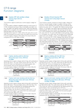
      CB Impulse-OFF with auxiliary voltage                                                      CE  Impulse-ON and impulse-OFF
                                                                                                     (Interval and trailing edge interval)
1 (Trailing edge interval)                                                                           CT-MXS

                  CT-MVS                                                                         This function requires continuous control supply voltage for

      This function requires continuous control supply voltage for                               timing. If control supply voltage is applied, closing control
      timing.
      If control supply voltage is applied, opening control input A1-                            input A1-Y1/B1 energizes the output relay immediately and
      Y1/B1 energizes the output relay immediately and starts tim-
      ing. The green LED flashes during timing. When the selected                                starts the pulse time t1. The green LED flashes during timing.
      pulse time is complete, the output relay de-energizes and the                              When t1 is complete, the output relay de-energizes and the
      flashing green LED turns steady.                                                           flashing green LED turns steady. Re-opening control input
      Closing control input A1-Y1/B1, before the pulse time is com-
      plete, de-energizes the output relay and resets the pulse time.                            A1-Y1/B1 energizes the output relay immediately and starts
      If control supply voltage is interrupted, the output relay de-
      energizes and the time delay is reset.                                                     the pulse time t2. The green LED flashes during timing. When

                                                                                                 t2 is complete, the output relay de-energizes and the flashing
                                                                                                 green LED turns steady. t1 and t2 are independently adjust-
                                                                                                 able. If control input A1-Y1/B1 changes state before the pulse

                                                                                                 time is complete, the output relay de-energizes and the pulse

             A1-A2                                                           2CDC 252 027 F0206  time is reset. If control input A1-Y1/B1 changes state again,
        A1-Y1/B1
    15-18, 25-28                                                                                 the interrupted pulse time restarts. If control supply voltage is
    15-16, 25-26
                                                                                                 interrupted, the output relay de-energizes and the time delay
             21-24
             21-22                                                                               is reset.                                                             2CDC 252 028 F0206
       green LED                                                                                                              A1-A2

                                                t  <t                                                A1-Y1/B1

                    t = adjusted pulse time                                                          15-18, 25-28
                                                                                                     15-16, 25-26

                                                                                                     green LED

                                                                                                                                     t1 t2                       < t1

                                                                                                                                     t1 = adjusted pulse time 1
                                                                                                                                     t2 = adjusted pulse time 2

DA Flasher, starting with the ON time                                                            DB Flasher, starting with the OFF time

    (Recycling equal times, ON first)                                                                (Recycling equal times, OFF first)

    CT-WBS                                                                                           CT-WBS

Applying control supply voltage starts timing with symmetrical                                   Applying control supply voltage starts timing with symmetri-
ON & OFF times. The cycle starts with an ON time first. The                                      cal ON & OFF times. The cycle starts with an OFF time first.
ON & OFF times are displayed by the flashing green LED,                                          The ON & OFF times are displayed by the flashing green
which flashes twice as fast during the OFF time.                                                 LED, which flashes twice as fast during the OFF time.
If control supply voltage is interrupted, the output relay de-                                   If control supply voltage is interrupted, the output relay de-
energizes and the time delay is reset.                                                           energizes and the time delay is reset.

             A1-A2                                                           2CDC 252 029 F0206               A1-A2                                                    2CDC 252 030 F0206
    15-18, 25-28                                                                                     15-18, 25-28
    15-16, 25-26                                                                                     15-16, 25-26

       green LED                                                                                        green LED

                    tt                                                                                                               tt

                    t = adjusted flashing time                                                                                       t = adjusted flashing time

DA  Flasher with reset, starting with the ON time                                                DB  Flasher with reset, starting with the OFF time
    (Recycling equal times with reset, ON first)                                                     (Recycling equal times with reset, OFF first)
    CT-MFS, CT-MBS                                                                                   CT-MFS, CT-MBS

Applying control supply voltage starts timing with symmetrical                                   Applying control supply voltage starts timing with symmetri-
                                                                                                 cal ON & OFF times. The cycle starts with an OFF time first.
ON & OFF times. The cycle starts with an ON time first. The                                      The ON & OFF times are displayed by the flashing green LED,
                                                                                                 which flashes twice as fast during the OFF time.
ON & OFF times are displayed by the flashing green LED,                                          The time delay can be reset by closing control input Y1-Z2.
                                                                                                 Opening control input Y1-Z2 starts the timer pulsing again
which flashes twice as fast during the OFF time.                                                 with symmetrical ON & OFF times.
                                                                                                 If control supply voltage is interrupted, the output relay de-
The time delay can be reset by closing control input Y1-Z2.                                      energizes and the time delay is reset.

Opening control input Y1-Z2 starts the timer pulsing again

with symmetrical ON & OFF times.

If control supply voltage is interrupted, the output relay de-

energizes and the time delay is reset.

    A1-A2                                                2CDC 252 031 F0206

    Y1-Z2                                                                                                     A1-A2                                                    2CDC 252 032 F0206

    15-18, 25-28                                                                                              Y1-Z2
    15-16, 25-26                                                                                     15-18, 25-28
                                                                                                     15-16, 25-26
    21-24
    21-22                                                                                                     21-24
                                                                                                              21-22
    green LED                                                                                           green LED

                    tt                             tt                                                                               tt

                                                                                                                                                                 tt

                  t = adjusted flashing time

                                                                                                                                     t = adjusted flashing time

1/45 ABB | Catalog Electronic Products and Relays 2015 | 2CDC 110 004 C0210
   51   52   53   54   55   56   57   58   59   60   61