
Page 59 - EPR Catalog 2015
P. 59
CT-S range
Function diagrams
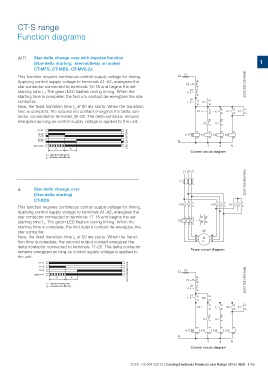
FC Star-delta change-over with impulse function
(Star-delta starting, interval/delay on make)
CT-MFS, CT-MBS, CT-MVS.2x 1
This function requires continuous control supply voltage for timing. L1 F3 2CDC 252 129 F0b06
Applying control supply voltage to terminals A1-A2, energizes the F2 95
S1
star contactor connected to terminals 15-18 and begins the set 96
0 21
starting time t1. The green LED flashes during timing. When the
starting time is complete, the first c/o contact de-energizes the star 22
contactor. S2 13 53
I
Now, the fixed transition time t2 of 50 ms starts. When the transition K2
time is complete, the second c/o contact energizes the delta con- 14
54
tactor connected to terminals 25-28. The delta contactor remains
K1T 15 25 13 13
energized as long as control supply voltage is applied to the unit. 18
K2 K1
28 14 14
22 22
K3 21 K1 21
A1-A2 2CDC 252 039 F0206 K1T A1 A1 A1 A1
15-18 A2
15-16 K1 K3 K2
25-28
25-26 A2 A2 A2
green LED N
Y ͬN
t1 t2
Control circuit diagram
t1 = adjusted starting time
t2 = transition time (50 ms)
L1 L2 L3 2CDC 253 009 F0012
135
-F1
246
F Star-delta change-over 135 135 135
(Star-delta starting)
CT-SDS -K2 2 4 6
This function requires continuous control supply voltage for timing. -K3 2 4 6 -K1 2 4 6
Applying control supply voltage to terminals A1-A2, energizes the 154 97 95
98 96
star contactor connected to terminals 17-18 and begins the set -F2
starting time t1. The green LED flashes during timing. When the 326
starting time is complete, the first output contact de-energizes the
-M1 W2
star contactor. V2
W1 U2
Now, the fixed transition time t2 of 50 ms starts. When the transi-
tion time is complete, the second output contact energizes the V1 M
U1 3 ~
delta contactor connected to terminals 17-28. The delta contactor
Power circuit diagram
remains energized as long as control supply voltage is applied to
the unit.
A1-A2 2CDC 252 040 F0206 L1 F3 2CDC 252 128 F0b06
17-18
17-28
green LED
t1 t2 95
t1 = adjusted starting time F2 96
t2 = transition time (50 ms) S1 21
0 22
S2 13 53
I
K2
14
54
K1T 17 17 13 13
18
K2 K1
28 14 14
22 22
K3 21 K1 21
A1 A1 A1 A1
K1T K1 K3 K2
A2 A2 A2 A2
N
Y ͬN
Control circuit diagram
2CDC 110 004 C0210 | Catalog Electronic Products and Relays 2015 | ABB 1/48