
Page 58 - EPR Catalog 2015
P. 58
CT-S range
Function diagrams
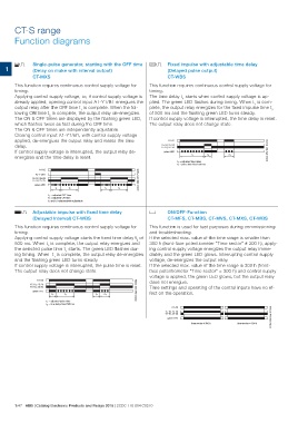
EC Single-pulse generator, starting with the OFF time AC Fixed impulse with adjustable time delay
(Delay on make with interval output) (Delayed pulse output)
1 CT-MXS CT-WBS
This function requires continuous control supply voltage for This function requires continuous control supply voltage for
timing.
Applying control supply voltage, or, if control supply voltage is timing.
already applied, opening control input A1-Y1/B1 energizes the
output relay after the OFF time t1 is complete. When the fol- The time delay t1 starts when control supply voltage is ap-
lowing ON time t2 is complete, the output relay de-energizes. plied. The green LED flashes during timing. When t1 is com-
The ON & OFF times are displayed by the flashing green LED, plete, the output relay energizes for the fixed impulse time t2
which flashes twice as fast during the OFF time. of 500 ms and the flashing green LED turns steady.
The ON & OFF times are independently adjustable.
Closing control input A1-Y1/B1, with control supply voltage If control supply voltage is interrupted, the time delay is reset.
applied, de-energizes the output relay and resets the time
delay. The output relay does not change state.
If control supply voltage is interrupted, the output relay de-
energizes and the time delay is reset. A1-A2 2CDC 252 041 F0206
15-18, 25-28
15-16, 25-26
green LED
t1 t2 < t1
t1 = adjusted time delay
t2 = pulse time fixed 500 ms
A1-A2 2CDC 252 037 F0206
A1-Y1/B1
15-18, 25-28
15-16, 25-26
green LED
t1 t2 t1 t2
t1 = adjusted OFF time
t2 = adjusted ON time
t1 and t2 independently adjustable
BC Adjustable impulse with fixed time delay G ON/OFF-Function
(Delayed Interval) CT-WBS CT-MFS, CT-MBS, CT-MVS, CT-MXS, CT-WBS
This function requires continuous control supply voltage for This function is used for test purposes during commissioning
timing. and troubleshooting.
Applying control supply voltage starts the fixed time delay t2 of If the selected max. value of the time range is smaller than
500 ms. When t2 is complete, the output relay energizes and 300 h (front-face potentiometer “Time sector” 300 h), apply-
the selected pulse time t1 starts. The green LED flashes dur- ing control supply voltage energizes the output relay imme-
ing timing. When t1 is complete, the output relay de-energizes diately and the green LED glows. Interrupting control supply
and the flashing green LED turns steady. voltage, de-energizes the output relay.
If control supply voltage is interrupted, the pulse time is reset. If the selected max. value of the time range is 300 h (front-
The output relay does not change state. face potentiometer “Time sector” = 300 h) and control supply
voltage is applied, the green LED glows, but the output relay
A1-A2 2CDC 252 042 F0206 does not energize.
Time settings and operating of the control inputs have no ef-
15-18, 25-28 fect on the operation.
15-16, 25-26
green LED
t2 t1 t2 < t1
t1 = adjusted pulse time
t2 = time delay fixed 500 ms
A1-A2 2CDC 252 044 F0206
15-18, 25-28
15-16, 25-26
green LED
Time sector ≠ 300 h Time sector = 300 h
1/47 ABB | Catalog Electronic Products and Relays 2015 | 2CDC 110 004 C0210