
Page 57 - EPR Catalog 2015
P. 57
CT-S range
Function diagrams
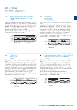
DE Flasher, starting with the ON or OFF time H Pulse former 1
(Recycling equal times, ON or OFF first)
CT-MVS (Single shot)
Applying control supply voltage starts timing with symmetri- CT-MFS, CT-MBS
cal ON & OFF times. The cycle starts with an ON time first.
Closing control input A1-Y1/B1, with control supply voltage This function requires continuous control supply voltage for
applied, starts the cycle with an OFF time first. The ON & timing.
OFF times are displayed by the flashing green LED, which Closing control input Y1-Z2 energizes the output relay im-
flashes twice as fast during the OFF time. mediately and starts timing. Operating the control contact
If control supply voltage is interrupted, the output relay de- switch Y1-Z2 during the time delay has no effect. The green
energizes and the time delay is reset. LED flashes during timing. When the selected ON time is
complete, the output relay de-energizes and the flashing
A1-A2 2CDC 252 033 F0206 green LED turns steady. After the ON time is complete, it
A1-Y1/B1 can be restarted by closing control input Y1-Z2.
15-18, 25-28 If control supply voltage is interrupted, the output relay de-
15-16, 25-26 energizes and the time delay is reset.
21-24 A1-A2 2CDC 252 034 F0206
21-22 Y1-Z2
green LED 15-18, 25-28
15-16, 25-26
tt tt 21-24
21-22
t = adjusted flashing time green LED
t t
t = adjusted pulse time
H Pulse former ED Pulse generator, starting with the ON or OFF time
(Single shot) (Recycling unequal times, ON or OFF first)
CT-MVS CT-MXS
This function requires continuous control supply voltage for This function requires continuous control supply voltage for
timing. timing.
Closing control input A1-Y1/B1 energizes the output relay Applying control supply voltage, with open control input
immediately and starts timing. Operating the control contact A1-Y1/B1, starts timing with an ON time t2 first. Applying
switch A1-Y1/B1 during the time delay has no effect. The control supply voltage, with closed control input A1-Y1/B1,
green LED flashes during timing. When the selected ON time starts timing with an OFF time t1 first. The ON & OFF times
is complete, the output relay de-energizes and the flashing are displayed by the flashing green LED, which flashes twice
green LED turns steady. After the ON time is complete, it as fast during the OFF time.
can be restarted by closing control input A1-Y1/B1. The ON & OFF times are independently adjustable.
If control supply voltage is interrupted, the output relay de- If control supply voltage is interrupted, the output relay de-
energizes and the time delay is reset. energizes and the time delay is reset.
A1-A2 2CDC 252 035 F0206 A1-A2 2CDC 252 075 F0207
A1-Y1/B1 A1-Y1/B1
15-18, 25-28 15-18, 25-28
15-16, 25-26 15-16, 25-26
green LED
21-24
21-22 t1 t2 t2 t1
green LED
t t t1 = adjusted OFF time
t2 = adjusted ON time
t = adjusted pulse time
2CDC 110 004 C0210 | Catalog Electronic Products and Relays 2015 | ABB 1/46