
Page 85 - EPR Catalog 2015
P. 85
Current and voltage monitoring relays, single-phase
Function diagrams
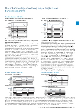
Function diagrams - CM-SFS.2 Current window monitoring 1x2 c/o contact j
Current window monitoring 1x2 c/o contact j OFF-delayed B without latching e
ON-delayed A without latching f
2CDC 252 216 F0205
2CDC 252 217 F0205
A1-A2 A1-A2
Thresholdmax Thresholdmax 2
Hysteresis Hysteresis
Measured value TS TV < TV Measured value TS TV TV
Hysteresis Hysteresis
Thresholdmin Thresholdmin
Open-circuit principle open Open-circuit principle open
11-14 (15-18) 11-14 (15-18)
11-12 (15-16) 11-12 (15-16)
21-24 (25-28) 21-24 (25-28)
21-22 (25-26) 21-22 (25-26)
green LED
green LED red LED
yellow LED
red LED
Closed-circuit principle closed
yellow LED 11-14 (15-18)
11-12 (15-16)
Closed-circuit principle closed 21-24 (25-28)
11-14 (15-18) 21-22 (25-26)
11-12 (15-16) green LED
21-24 (25-28) red LED
21-22 (25-26) yellow LED
green LED
red LED
yellow LED
Further function diagrams see data sheet.
ON-delayed A current window monitoring with parallel OFF-delayed B current window monitoring with parallel
switching c/o contacts j: switching c/o contacts j:
If the measured value exceeds resp. drops below the adjusted If the measured value exceeds resp. drops below the adjusted
threshold value before the set start-up delay TS is complete, threshold value when the set start-up delay TS is complete,
the output relays do not change their actual state. the output relays energize h / de-energize g, when B is
If the measured value exceeds resp. drops below the adjusted configured, and remain in this position during the set tripping
threshold value when TS is complete, the tripping delay TV delay TV. If the measured value exceeds resp. drops below the
starts, when A is configured. If TV is complete and the mea- threshold value plus resp. minus the fixed hysteresis (5%) and
sured value is still exceeding resp. below the threshold value the latching function is not activated e, the tripping delay TV
minus resp. plus the fixed hysteresis (5%), the output relays starts. After completion of TV, the output relays de-energize
energize h /de-energize g. h / energize g, provided that the latching function is not
If the measured value exceeds resp. drops below the thresh- activated e. With activated latching function f the out-
old value plus resp. minus the hysteresis and the latching put relays remain energized h and de-energize only, when
function is not activated f, the output relays de-energize h the supply voltage is interrupted / the output relays remain
/ energize g. With activated latching function e the output de-energized g and energize only, when the supply voltage
relays remain energized h and de-energize only, when the is switched off and then again switched on = Reset. When
supply voltage is interrupted / the output relays remain de- i is adjusted on the device, the functionality is equivalent
energized g and energize only, when the supply voltage is to the one described above. There is only to consider that in
switched off and then again switched on = Reset. this case, instead of both output relays, only one output relay
each will be switched.
“>I“ = 1115-1216/1418 ; “<I“ = 2125-2226/2428
Function diagrams - CM-ESS.1 Function diagrams - CM-ESS.2
Overvoltage monitoring d Overvoltage monitoring d
2CDC 252 208 F0205 A1-A2 2CDC 252 210 F0205
A1-A2 Threshold TV < TV
Hysteresis < TV
Threshold Measured value
Hysteresis
Measured value 11-14 (15-18)
11-14 (15-18) 11-12 (15-16)
11-12 (15-16) 21-24 (25-28)
green LED 21-22 (25-26)
red LED green LED
yellow LED red LED
Undervoltage monitoring c yellow LED
A1-A2 2CDC 252 209 F0205 Undervoltage monitoring c
Measured value A1-A2 2CDC 252 211 F0205
Hysteresis
Measured value TV
Hysteresis
Threshold Threshold
11-14 (15-18) 11-14 (15-18)
11-12 (15-16) 11-12 (15-16)
green LED 21-24 (25-28)
21-22 (25-26)
red LED green LED
yellow LED red LED
yellow LED
Depending on the configuration, the voltage monitoring relays CM-ESS.1 and CM-ESS.2 can be used for over- d or undervolt-
age monitoring c in single-phase AC and/or DC systems. The voltage to be monitored (measured value) is applied to terminals
B-C. The devices work according the open-circuit principle. If the measured value exceeds resp. drops below the adjusted
threshold value, the output relay(s) energize(s): on the CM-ESS.1 immediately, on the CM-ESS.2 after the set tripping delay
TV. If the measured value exceeds resp. drops below the threshold value plus resp. minus the adjusted hysteresis, the output
relay(s) de-energize(s). The hysteresis is adjustable within a range of 3-30 % of the threshold value.
2CDC 110 004 C0210 | Catalog Electronic Products and Relays 2015 | ABB 2/18