
Page 88 - EPR Catalog 2015
P. 88
Current and voltage monitoring relays, single-phase
Connection diagrams, DIP switches
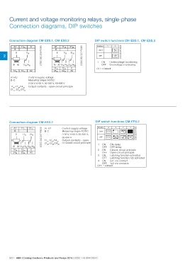
Connection diagram CM-ESS.1, CM-ESS.2 DIP switch functions CM-ESS.1, CM-ESS.2
1 ON Undervoltage monitoring
OFF Overvoltage monitoring
OFF = Default
A1 1115 C A12CDC 252 206 F00051115 2125
B B 2CDC 252 207 F00051115 2125
B 1115 B 2CDC 252 275 F0005
2 C
C
A1 A2 1216 1418 A1 A2 1216 1418 2226 2428
1418 1216 A2 1418 1216 C
2428 2226 A2
A1-A2 Control supply voltage
B-C Measuring ranges AC/DC:
1115-1216/1418 3-30 V; 6-60 V; 30-300 V; 60-600 V
2125-2226/2428
Output contacts - open-circuit principle
Connection diagram CM-EFS.2 DIP switch functions CM-EFS.2
A1 1115 2125 A1-A22CDC 252 207 F0005 Position 4 3 2 1
B 1115 2125 B-C 2CDC 252 274 F0005
Control supply voltage ON 2x1 c/o closed
B 1115-1216/1418 Measuring ranges AC/DC:
2125-2226/2428 OFF 1x2 c/o open
C 3-30 V; 6-60 V; 30-300 V;
60-600 V 1 ON ON-delay
Output contacts - open- OFF OFF-delay
or closed circuit principle
2 ON Closed-circuit principle
A1 A2 1216 1418 2226 2428 OFF Open-circuit principle
1418 1216 C 3 ON Latching function activated
2428 2226 A2 OFF Latching function not activated
4 ON 2x1 c/o contact
OFF 1x2 c/o contacts
OFF = Default
2/21 ABB | Catalog Electronic Products and Relays 2015 | 2CDC 110 004 C0210