
Page 89 - EPR Catalog 2015
P. 89
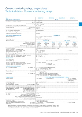
Current monitoring relays, single-phase
Technical data - Current monitoring relays

Type                                                                      CM-SRS.1                    CM-SRS.2                  CM-SRS.M          CM-SFS.2
Input circuit - Supply circuit
Rated control supply voltage Us                         A1-A2 110-130 V AC                                              A1-A2
                                                        A1-A2 220-240 V AC
Rated control supply voltage Us tolerance               A1-A2 24-240 V AC/DC                                                                                               2
Rated frequency
                                                                   -15...+10 %
Current / power consumption                     AC versions 50/60 Hz
Power failure buffering time               AC/DC versions 50/60 Hz or DC
Transient overvoltage protection
                                                                   see data sheets
                                                                   20 ms
                                                                   Varistors

Input circuit - Measuring circuit                                                                              B1/B2/B3-C
Monitoring function
                                                                     over- or undercurrent monitoring                                     over- and under-
Measuring method                                                     configurable                                                         current monitoring

                                                                     True RMS measuring principle

Measuring inputs                                                                    CM-SxS.x1                                       CM-SxS.x2

                                             Terminal connection       B1-C            B2-C                     B3-C      B1-C             B2-C        B3-C
                                     Measuring ranges AC/DC          3-30 mA        10-100 mA                  0.1-1 A  0.3-1.5 A         1-5 A      3-15 A 2)
                                                                                                                0.1 ⏲                     0.01 ⏲     0.0025 ⏲
                                                   Input resistance    3.3 ⏲             1⏲                              0.05 ⏲            50 A
                              Pulse overload capacity t < 1 s        500 mA              1A                     10 A       15 A                        100 A

                                           Continous capacity 50 mA                        150 mA              1.5 A            2A        7 A 17 A

Threshold value(s)                                                   adjustable within the indicated measuring range

Setting accuracy of threshold value                                  10 %

Hysteresis related to the threshold value                            3-30 % adjustable                                                    5 % fixed

Measuring signal frequency range                                     DC / 15 Hz - 2 kHz
Rated measuring signal frequency range                               DC / 50-60 Hz
Maximum response time                                                AC: 80 ms / DC: 120 ms
Accuracy within the control supply voltage tolerance                 ͬU ͨ 0.5 %
Accuracy within the temperature range                                ͬU ͨ 0.06 % / °C

Timing circuit

Start-up delay TS                                                    none                                               0 or 0.1-30 s adjustable

Tripping delay TV                                                    none                  0 or 0.1-30 s adjustable

Repeat accuracy (constant parameters)                                Ȁ0.07 % of full scale
Accuracy within the control supply voltage tolerance                 - ͬt ͨ 0.5 %
Accuracy within the temperature range                                - ͬt ͨ 0.06 % / °C

Indication of operational states

Control supply voltage                     U/T: green LED V: control supply voltage applied,

Measured value                                                       X:    s t a r t- u p  delay  TS  active,
Relay status                                                         W:    tripping        delay  TV  active

                                           I: red LED V: overcurrent,

                                                                     W: undercurrent

                                           R: yellow LED V: relay energized, no latching function

                                                                     Z: relay energized, active latching function

                                                                     Y: relay de-energized, active latching function

Output circuits                                                                            11(15)-12(16)/14(18), 21(25)-22(26)/24(28) - Relays

Kind of output                                                       1 c/o contact         2 c/o contacts                                 1x2 c/o contacts
                                                                                                                                          or 2x1 c/o contact
                                                                                                                                          configurable

Operating principle                                                  open-circuit principle 1)                          open- or closed-circuit principle configurable 1)

Contact material                                                     AgNi

Rated operational voltage Ue               IEC/EN 60947-1 250 V

Minimum switching voltage / minimum switching current                24 V / 10 mA

Maximum switching voltage / maximum switching current 250 V AC / 4 A AC

Rated operational current Ie        AC-12 (resistive) at 230 V 4 A
(IEC/EN 60947-5-1)                 AC-15 (inductive) at 230 V 3 A

                                         DC-12 (resistive) at 24 V 4 A

                                     DC-13 (inductive) at 24 V 2 A

AC rating                                      Utilization category B 300
(UL 508)                          (Control Circuit Rating Code)

                              max. rated operational voltage 300 V AC

                    max. continuous thermal current at B 300 5 A

                     max. making/breaking apparent power 3600/360 VA
                                            (Make/Break) at B 300

Mechanical lifetime                                                  30x106 switching cycles
Electrical lifetime (AC-12, 230 V, 4 A)                              0.1x10⁶ switching cycles

Max. fuse rating to achieve short-circuit  n/c contact 6 A fast-acting                     10 A fast-acting                               6 A fast-acting
protection                                 n/o contact 10 A fast-acting

1) Open-circuit principle: output relay energizes if the measured value exceeds b / falls below a the adjusted threshold value
  Closed-circuit principle: output relay de-energizes if measured value exeeds b / falls below a the adjusted threshold value

2) In case of measured currents > 10 A, lateral spacing has to be min. 10 mm

                                                                           2CDC 110 004 C0210 | Catalog Electronic Products and Relays 2015 | ABB 2/22