Page 49 - index
P. 49
AC500-eCo
System data
Environmental conditions
Process and supply voltages
24 V DC Process and supply voltage 24 V DC (-15 %, +20 % without ripple)
Absolute limits 19.2...30 V inclusive ripple
Ripple < 5 %
Protection against reverse polarity 10 s
120 V AC Line voltage 120 V AC (-15 %, +10 %)
Frequency 47...62.4 Hz / 50...60 Hz (-6 %, +4 %)
230 V AC Line voltage 230 V AC (-15 %, +10 %) 3
Frequency 47...62.4 Hz / 50...60 Hz (-6 %, +4 %)
120–240 V AC Wide-range supply
Line voltage 102...264 V / 120..240 V (-15 %, +10 %)
Frequency 47...62.4 Hz / 50...60 Hz (-6 %, +4 %)
Allowed interruptions of power supply
DC supply Interruption < 10 ms, time between 2 interruptions > 1 s, PS2
AC supply Interruption < 0.5 periods, time between 2 interruptions > 1 s
Important: Exceeding the maximum power supply voltage (>30 V DC) for process or supply voltages could lead to unrecoverable damage of the system. The system could be destroyed.
The creepage distances and clearances meet the requirements of the overvoltage category II, pollution degree 2.
For the supply of the modules, power supply units according to PELV specifcations must be used.
Climatic conditions
Temperature Operation 0...60 °C (horizontal mounting of modules)
0...40 °C (vertical mounting of modules and output load reduced to 50 % per group)
Storage -40...+70 °C
Transport -40...+70 °C
Humidity Without condensation Max. 95 %
Air pressure Operation > 800 hPa / < 2000 m
Storage > 660 hPa / < 3500 m
Electromagnetic Compatibility
Radiated emission (radio disturbances) Acc. to IEC61000-6-4
Conducted emission (radio disturbances) Acc. to IEC61000-6-4
Electrostatic discharge (ESD) Acc. to EN 61000-4-2, zone B, criterion B
Fast transient interference voltages (burst) Acc. to EN 61000-4-4, zone B, criterion B
High energy transient interference voltages (surge) Acc. to EN 61000-4-5, zone B, criterion B
Infuence of radiated disturbances Acc. to IEC 61000-4-3, zone B, criterion A
Infuence of line-conducted interferences Acc. to IEC 61000-4-6, zone B, criterion A
In order to prevent operating malfunctions, it is recommended, that the operating personnel discharge themselves prior to touching communication connectors or perform other
suitable measures to reduce effects of electrostatic discharges. The connector of the I/O-Bus must not be touched during operation.
Mechanical data
Wiring method Available types of terminal Spring terminals, screw terminals
Degree of protection IP 20 (if all terminal screws are tightened)
Vibration resistance Acc. to IEC 61131-2
Shock resistance Acc. to IEC 60068-2-27
Assembly position Horizontal no derating
Vertical max. ambient temp. 40°C and output load reduced to 50% per group
Assembly on DIN rail Acc. to IEC 60715
DIN rail type 35 mm, depth 7.5 mm or 15 mm
Assembly with screws Screw diameter 4 mm
Fastening torque 1.2 Nm
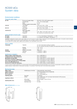
Main dimensions mm, inches
82 3.23” 34 1.34”
135 5.31” 135 5.31”
75 2.96”
75 2.96”
ABB Industrial Automation & Motion | 3/47