Page 79 - index
P. 79
AC500
Technical data
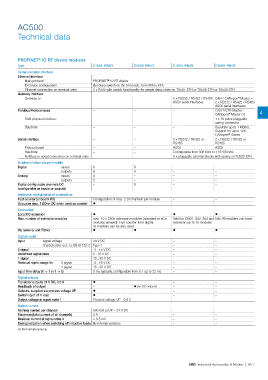
PROFINET IO RT device modules
®
Type CI501-PNIO CI502-PNIO CI504-PNIO CI506-PNIO
Communication interface
Ethernet Interface
Main protocol PROFINET IO RT device
®
ID Device configuration By rotary switch on the front side, from 00h to FFh
Ethernet connection on terminal units 2 x RJ45 with switch functionality for simple daisy chain on TU507-ETH or TU508-ETH or TU520-ETH
Gateway Interface
Gateway to – – 3 x RS232 / RS422 / RS485 CAN / CANopen Master +
®
ASCII serial interfaces 2 x RS232 / RS422 / RS485
ASCII serial interfaces
Fieldbus Protocol used – – – CAN 2A/2B Master - 4
CANopen Master (1)
®
CAN physical interface – – – 1 x 10 poles pluggable
spring connector
Baudrate – – – Baudrate up to 1 MBit/s,
Support for up to 126
®
CANopen Slaves
Serial interface – – 3 x RS232 / RS422 or 2 x RS232 / RS422 or
RS485 RS485
Protocol used – – ASCII ASCII
Baudrate – – Configurable from 300 bit/s to 115200 bit/s
Fieldbus or serial connection on terminal units – – 3 x pluggable terminal blocks with spring on TU520-ETH
Number of channels per module
Digital inputs 8 8 – –
outputs 8 8 – –
Analog inputs 4 – – –
outputs 2 – – –
Digital confgurable channels DC – 8 – –
(confgurable as inputs or outputs)
Additional confguration of channels as
Fast counter (onboard I/O) Configuration of max. 2 DI channels per module – –
Occupies max. 1 DO or DC when used as counter ? – –
Connection
Local I/O extension ? ? ?
Max. number of extension modules max. 10 x S500 extension modules (standard or eCo Valid for CI501, 502, 504 and 506. All modules can have
modules allowed). Fast counter from digital extension up to 10 modules
IO modules can be also used.
Via terminal unit TU5xx ? ? ? ?
Digital inputs
Input signal voltage 24 V DC – –
characteristic acc. to EN 61132-2 Type 1 – –
0 signal -3...+5 V DC – –
Undefned signal state 5...15 V DC – –
1 signal 15...30 V DC – –
Residual ripple, range for 0 signal -3...+5 V DC – –
1 signal 15...30 V DC – –
Input time delay (0 -> 1 or 1 -> 0) 8 ms typically, configurable from 0.1 up to 32 ms – –
Digital outputs
Transistor outputs 24 V DC, 0.5 A ? – –
Readback of output – ? (on DC outputs) – –
Outputs, supplied via process voltage UP ? – –
Switching of 24 V load ? – –
Output voltage at signal state 1 Process voltage UP - 0.8 V – –
Output current
Nominal current per channel 500 mA at UP = 24 V DC – –
Maximum (total current of all channels) 8 A – –
Residual current at signal state 0 < 0.5 mA – –
Demagnetization when switching off inductive loads By internal varistors – –
(1) Not simultaneously.
ABB Industrial Automation & Motion | 4/77