
Page 126 - PLC Automation
P. 126
124 MAIN CATALOG PLC AUTOMATION
—
AC500
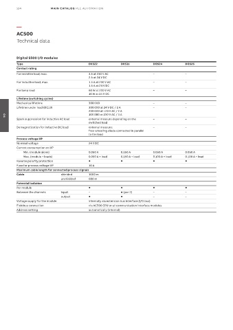
Technical data
Digital S500 I/O modules
Type DX522 DX531 DO524 DO526
Contact rating
For resistive load, max. 3 A at 230 V AC – –
2 A at 24 V DC
For inductive load, max. 1.5 A at 230 V AC – –
1.5 A at 24 V DC
For lamp load 60 W at 230 V AC – –
10 W at 24 V DC
Lifetime (switching cycles)
Mechanical lifetime 300 000 – –
Lifetime under load (DC13) 300 000 at 24 V DC / 2 A – –
200 000 at 120 V AC / 2 A
100 000 at 230 V AC / 3 A
Spark suppression for inductive AC load external measure depending on the – –
04
switched load
Demagnetization for inductive DC load external measure: – –
free-wheeling diode connected in parallel
to the load
Process voltage UP
Nominal voltage 24 V DC
Current consumption on UP
Min. (module alone) 0.050 A 0.150 A 0.050 A 0.050 A
Max. (module + loads) 0.050 A + load 0.150 A + load 0.100 A + load 0.100 A + load
Reverse polarity protection
Fuse for process voltage UP 10 A
Maximum cable length for connected process signals
Cable shielded 1000 m
unshielded 600 m
Potential isolation
Per module
Between the channels input – (per 2) – –
output – –
Voltage supply for the module internally via extension bus interface (I/O bus)
Fieldbus connection via AC500 CPU or all communication interface modules
Address setting automatically (internal)