
Page 122 - PLC Automation
P. 122
120 MAIN CATALOG PLC AUTOMATION
—
AC500
Technical data
AC500 V3 CPUs
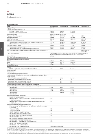
Type PM5630-2ETH PM5650-2ETH PM5670-2ETH PM5675-2ETH
Supply voltage 24 V DC
Current consumption on 24 V DC
Min. typ. (module alone) 0.110 A 0.120 A 0.140 A
Max. typ. (all couplers and I/Os) 0.850 A 0.900 A 0.950 A
Type of processor TI ARM Cortex-A9 32-bit-RISC
Processor clock frequency 300 MHz 600 MHz 1 GHz 1 GHz
Total RAM memory 128 MB 256 MB 512 MB 512 MB
Total Flash memory 128 MB 512 MB 1024 MB 1024 MB
Total user program memory (4) 8 MB 80 MB 160 MB
Thereof User program code and data (dynamically allocated) 2 MB (3) 8 MB (3) 32 MB (3) 32 MB (3)
Thereof User web server Data max. 6 MB 72 MB 128 MB 128 MB
User data memory saved 256 KB 256 KB 1.5 MB 1.5 MB
Thereof VAR Retain persistent 128 kB 128 kB 1024 kB 1024 kB
Thereof %M memory (e.g. Modbus register memory) 128 kB 128 kB 512 kB 512 kB
04
User flash disk (data-storage, programm access or also external with FTP) 8 GB Flash non
removable
Plug-in memory card Depending on memory card used: use MC5102 for standard usage or
MC5141 for high requirements, MC502 not for future project
Data buffering battery
Real-time clock (with battery back-up)
Cycle time for 1 instruction (minimum)
Binary 0.02 µs 0.01 µs 0.002 µs
Word 0.03 µs 0.01 µs 0.002 µs
Floating-point 0.12 µs 0.01 µs 0.002 µs
Program execution
Cyclical
Minimun cycle time configurable for cyclical task 1 ms 1 ms 0.5 ms
Time controlled
Multi tasking
User program protection by password
Motion control with EtherCAT or CAN sync onboard and PLCopen library
PS5611-MC(2)
Min. EtherCAT master cycle time 2 ms 1 ms 0.5 ms
Number of synchronized axis (5) in 1 ms - 8 16
Number of synchronized axis (5) in 2 ms 4 16 32
Number of synchronized axis (5) in 4 ms 8 32 64
Communication modules and terminal bases supported
Max. number of communication modules on terminal base TB
TB5600-2ETH 0 slot 0 slot 0 slot
TB5610-2ETH 1 slot 1 slot 1 slot
TB5620-2ETH 2 slots 2 slots 2 slots
TB5640-2ETH - 4 slots 4 slots
TB5660-2ETH - - 6 slots
Type of safety module supported
SM560-S - safety module
SM560-S-FD-1 - safety module with F-Device functionality for (1)
1 PROFIsafe network
SM560-S -FD-4 - safety module with F-Device functionality for (1)
1 PROFIsafe network
Type of communication module supported
Max. number of variables allowed for each communication module
supported
Input variables 4 kB 5 kB
Output variables 4 kB 5 kB
CM574-RS/RCOM - serial interface -
CM582-DP - PROFIBUS DP V0/V1 Slave (1)
CM592-DP - PROFIBUS DP V0/V1 Master (1)
CM579-ETHCAT - Master
CM579-PNIO - PROFINET IO RT controller
CM589-PNIO - PROFINET IO RT device (1)
CM589-PNIO-4 - PROFINET IO RT with 4 devices (1)
CM597-ETH - Ethernet interface -
CM588-CN - CAN, CANopen Slave -
CM598-CN - CAN, CANopen Master only CAN 2A/2B today
(1) In preparation (2) Recommandation
(3) Memory size of V2 versus V3 CPUs is not comparable. Projects have a different and separate User Program code and Data memory calculation in Automation Builder 2.4.0
version or later: System, configuration and web server parts are not counted anymore. This results in typically about 50 % lower memory usage compared to V2, and even lower
memory usage compared to V3 projects compiled in Automation Builder 2.3.0 or before.
(4) Total user program memory: contains user program code, data (dynamically allocated), web server memory and infrastructure (5) + 1 e.g. for virtual axis