
Page 124 - PLC Automation
P. 124
122 MAIN CATALOG PLC AUTOMATION
—
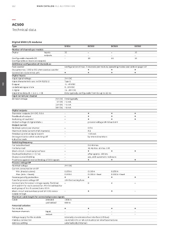
AC500
Technical data
Digital S500 I/O modules
Type DI524 DC522 DC523 DC532
Number of channels per module
Digital inputs 32 – – 16
outputs – – – –
Configurable channels DC – 16 24 16
(configurable as inputs or outputs)
Additional configuration of channels as
Fast counter configuration of max. 2 channels per module, operating modes see table on page 147
Occupies max. 1 DO or DC when used as counter –
Connection via terminal unit
Digital inputs
Input signal voltage 24 V DC
Input characteristic acc. to EN 61132-2 Type 1
0 signal -3...+5 V DC
04
Undefined signal state 5...15 V DC
1 signal 15...30 V DC
Input time delay (0 -> 1 or 1 -> 0) 8 ms typically, configurable from 0.1 up to 32 ms
Input current per channel
At input voltage 24 V DC 5 mA typically
5 V DC > 1 mA
15 V DC > 5 mA
30 V DC < 8 mA
Digital outputs
Transistor outputs 24 V DC, 0.5 A –
Readback of output –
Switching of load 24 V –
Output voltage at signal state 1 – process voltage UP minus 0.8 V
Output current
Nominal current per channel – 0.5 A
Maximum (total current of all channels) – 8 A
Residual current at signal state 0 – < 0.5 mA
Demagnetization when switching off – by internal varistors
inductive loads
Switching frequency
For inductive load – 0.5 Hz max.
For lamp load – 11 Hz max. at max. 5 W
Short-circuit / overload proofness –
Overload indication (I > 0.7 A) – after approx. 100 ms
Output current limiting – yes, with automatic reclosure
Proofness against reverse feeding of 24 V signals –
Process voltage UP
Nominal voltage 24 V DC
Current consumption on UP
Min. (module alone) 0.150 A 0.100 A 0.150 A
Max. (min. + loads) 0.150 A 0.100 A + load 0.150 A + load
Reverse polarity protection
Fuse for process voltage UP 10 A fast acting fuse
Connections for sensor voltage supply. Terminal – 8 4 –
24 V and 0 V for each connection. Permitted load for
each group of 4 or 8 connections: 0.5 A
Short-circuit and overload proof 24 V DC sensor – –
supply voltage
Maximum cable length for connected process signals
Cable shielded 1000 m
unshielded 600 m
Potential isolation
Per module
Between channels input – – – –
output – – – –
Voltage supply for the module internally via extension bus interface (I/O bus)
Fieldbus connection via AC500 CPU or all communication interface modules
Address setting automatically (internal)