
Page 206 - PLC Automation
P. 206
204 MAIN CATALOG PLC AUTOMATION
—
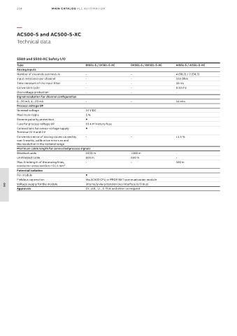
AC500-S and AC500-S-XC
Technical data
S500 and S500-XC Safety I/O
Type DI581-S / DI581-S-XC DX581-S / DX581-S-XC AI581-S / AI581-S-XC
Analog inputs
Number of channels per module - - 4 (SIL2) / 2 (SIL3)
Input resistance per channel - - 125 Ohm
Time constant of the input filter - - 10 ms
Conversion cycle - - 0.33 ms
Overvoltage protection - - -
Signal resolution for channel configuration
0...20 mA, 4...20 mA - - 14 bits
Process voltage UP
Nominal voltage 24 V DC
Maximum ripple 5 %
Reverse polarity protection
Fuse for process voltage UP 10 A miniature fuse
Connections for sensor voltage supply
Terminal 24 V and 0 V
Conversion error of analog values caused by - - ±1.5 %
non-linearity, calibration errors ex and
the resolution in the nominal range
Maximum cable length for connected process signals
Shielded cable 1000 m 1000 m -
Unshielded cable 600 m 600 m -
Max. line length of the analog lines, - - 100 m
conductor cross section > 0.14 mm²
Potential isolation
Per module
Fieldbus connection Via AC500 CPU or PROFINET communication module
Voltage supply for the module Internally via extension bus interface (I/O bus)
Approvals CE, cUL, UL, C-Tick and other on request
06