
Page 375 - Entrelec Terminal Blocks Master Catalog
P. 375
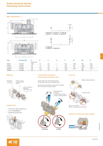
Power terminal blocks
         Mounting instructions


         Main dimensions mm


                                                                                                                      4

         Type          Mounting with:  A       B        C         D         F         G1       G2        H
                                     Dimensions mm
         D35/27...     2 Screws      100.5     7.5      6.5       /         63.5      136.5    160       82.5
         D70/32...     2 Screws      120       7.5      6.5       /         72.5      165      190.5     105.7
         D120/42...    2 Screws      120       7.5      6.5       /         83.5      197      255.5     129.7
         D185/55...    4 Screws      135       13.5     6.5       8.5       103.5     228.5    295       151.5
         D300/55...    4 Screws      135       13.5     6.5       8.5       105       /        295       /


         Marking                             Locking foot operating              Locking
                                             with screwdriver DIA. 4 mm
                                                                                                Between blocks with pins
         2 RC 810 or  RPC type setting       Center opening (to be made after jumper
         1 RC 1010  marker or RC 810         bar has been removed) "monostable action".
                   marker
                                             As soon as the screwdriver is removed, the locking
                                             foot comes back to closed position
                            2 slots, 2 RC810 not
                            separated or
                            1 RC 1010 in 1 slot
                                                               Side opening with
                                                               2 positions.                     With M3 screw
                                                               The locking foot remains
                                                               in open or closed position.


         Jumper bar                                                              M3 nut on one side
                                                                                 M3 nut + washer on the other side
            – move the marker holders up
            – cut out the partition
            – screw the jumper bar
                                                                                 Mounting of the derivative system


                                                                                                                    1SNC165014S0201


                                                 Unlocking        Locking


                                                                                                            PAGE 83