
Page 816 - Motor_protection_and_control_Manual_motor_starters_ contactors
P. 816
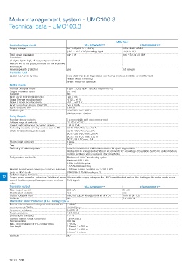
Motor management system - UMC100.3

       Technical data - UMC100.3


                                                                          UMC100.3
       Control voltage circuit                        1SAJ530000R0***                   1SAJ530000R1***
       Supply voltage                      24 V DC (+30 % ... -20 %)          110V - 240V AC/DC
                                           (19.2 ... 31.2 V DC) including ripple  -15% / +10%
       Total power dissipation             min. 3 W                           min P: 3.5 W / S: 8 W
       Conditions:
       all digital inputs high, all relay outputs activated
       Please refer to the product manual for more detailed
       information.
       Reverse polarity protection         yes                                not relevant
       Controller Unit
       LEDs: Red / green / yellow          Red: Motor has been tripped due to a thermal overload condition or another fault.
                                           Yellow: Motor is running
                                           Green: Ready for operation
       Digital inputs
       Number of digital inputs            6 (DI0 ... DI5) Type 1 accord. to EN 61131-2
       Supply for digital inputs           24 V DC
       Isolation                           No
       Input signal bounce suppression     Typ. 2 ms
       Signal 0 range including ripple     -31.2 ... +5 V
       Signal 1 range including ripple     +15 ... +31.2 V
       Input current per channel (24 V DC)  Typ. 6.0 mA
       Input resistor to 0 V               3.9 k Ω
       Cable length                        unshielded max. 600 m
                                           shielded max. 1000 m
       Relay Outputs
       Number of relay outputs             3 x monostable with one common root
       Voltage range of contacts           12-250 V AC/DC
       Lowest switched power for correct signals  1 W or 1 VA
       Switching capacity per relay contact acc. to EN   AC-15 240 V AC: max. 1.5 A
       60947-5-1 (electromagnetic load)    AC-15 120 V AC: max. 3 A
                                           DC-13 250 V DC max. 0.11 A
                                           DC-13 125 V DC max. 0.22 A
                                           DC-13 24 V DC max. 1 A
       Short-circuit protection            6 A gG
       U imp                               4 kV
       Switching of inductive power        Inductive loads need additional measures for spark suppression.
                                           Diodes for DC voltage and varistors / RC elements for AC voltage are suitable. Some DC coil contactors
                                           contain rectifiers which suppress sparks perfectly.
       Relay contact service life          Mechanical 500 000 switching cycles
                                           Electrical (250 V AC):
                                           0.5 A: 100 000 cycles
                                           1.5 A 50 000 switching
       Internal clearance and creepage distances relay con- > 5.5 mm (safety insulation up to 250 V AC)
       tacts to 24 V circuits              (EN 60947-1, Pollution degree 2)
       Pollution degree terminals          3
   12  Supply power down/up, behaviour: Valid for all motor  Whenever the supply voltage of the UMC is switched off and on, the starting of the motor needs a new
       control functions, except transparent and overload   RUN signal.
       relay.
       Transistor output                              1SAJ530000R0***                   1SAJ530000R1***
       Max. output current                 200 mA                             50 mA
       Short circuit protected             Yes                                Yes
       Output voltage if high              UMC100 supply voltage, nominal 24 V DC  nominal 24V DC
       Isolation                           No                                 3.4 - 3.8 kΩ
       Thermistor Motor Protection (PTC - binary) Type A
       Broken wire resistance Voltage at broken wires bet-  > 4.8 kΩ
       ween terminals T1/T2                12 V DC (typ.)
       Response resistance                 3.4-3.8 kΩ
       Reset resistance                    1.5-1.65 kΩ
       Short circuit resistance            < 21 Ω
       Current at short circuit conditions  1.5 mA (typ.)
       Response time                       800 ms
       Max. cold resistance of PTC sensor chain  < 1.5 kΩ
       Line length                         2.5 mm : 2 x 250 m
                                                2
                                           1.5 mm : 2 x 150 m
                                                2
                                           0.5 mm : 2 x 50 m
                                                2
       Isolation                           No


       12/12  |  ABB