
Page 507 - Motor protection and control Manual motor starters, contactors and overload relays
P. 507
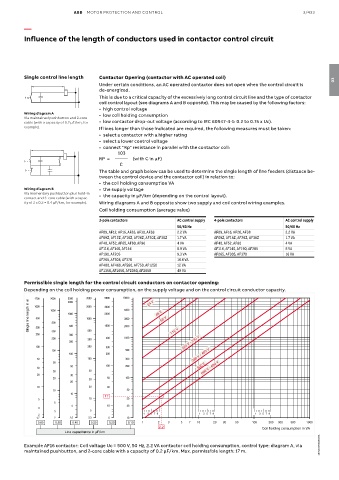
ABB  MOTOR PROTECTION AND CONTROL                                               3/433

          —

          Influence of the length of conductors used in contactor control circuit


          Single control line length  Contactor Opening (contactor with AC operated coil)                             03
                                    Under certain conditions, an AC operated contactor does not open when the control circuit is
                                    de-energized.
                                    This is due to a critical capacity of the excessively long control circuit line and the type of contactor
                              A841D  coil control layout (see diagrams A and B opposite). This may be caused by the following factors:
                                    •  high control voltage
          Wiring diagram A          •  low coil holding consumption
          Via maintained pushbutton and 2-core
          cable (with a capacity of 0.2 μF/km, for   •  low contactor drop-out voltage (according to IEC 60947-4-1: 0.2 to 0.75 x Uc).
          example).                 If lines longer than those indicated are required, the following measures must be taken:
                                    •  select a contactor with a higher rating
                                    •  select a lower control voltage
                                    •  connect "Rp" resistance in parallel with the contactor coil:
                                          103
                                    RP  =       (with C in µF)
                                           C
                                    The table and graph below can be used to determine the single length of line feeders (distance be-
                                    tween the control device and the contactor coil) in relation to:
                              A840D  •  the coil holding consumption VA
          Wiring diagram B          •  the supply voltage
          Via momentary pushbutton plus hold-in   •  the capacity in μF/km (depending on the control layout).
          contact and 3-core cable (with a capac-
          ity of 2 x 0.2 = 0.4 μF/km, for example).  Wiring diagrams A and B opposite show two supply and coil control wiring examples.
                                    Coil holding consumption (average value)

                                    3-pole contactors          AC control supply  4-pole contactors  AC control supply
                                                               50/60 Hz                              50/60 Hz
                                    AF09, AF12, AF16, AF26, AF30, AF38  2.2 VA  AF09, AF16, AF26, AF38  2.2 VA
                                    AF09Z, AF12Z, AF16Z, AF26Z, AF30Z, AF38Z  1.7 VA  AF09Z, AF16Z, AF26Z, AF38Z  1.7 VA
                                    AF40, AF52, AF65, AF80, AF96  4 VA      AF40, AF52, AF80         4 VA
                                    AF116, AF140, AF146        8.9 VA       AF116, AF140, AF190, AF205  8 VA
                                    AF190, AF205               9.3 VA       AF265, AF305, AF370      16 VA
                                    AF265, AF305, AF370        16.6 VA
                                    AF400, AF460, AF580, AF750, AF1250  12 VA
                                    AF1350, AF1650, AF2050, AF2650   48 VA
          Permissible single length for the control circuit conductors on contactor opening:
          Depending on the coil holding power consumption, on the supply voltage and on the control circuit conductor capacity.
             1700  2000  2500  3300   5000  10000    24 V
           Single line length in m  500  1000  1000  1000  2000  5000  48 V 60 V
                         2000
             1000
                               2000
                                      3000
                                             3000
                   500
              300
              200  300   500    500   1000   2000            110 V
                         300
                   200          300   500    1000
                         200                                     220 V - 230 V
              100               200   300
                   100                       500
                         100          200                            380 V - 400 V
              50                100          300
                    50
                          50          100    200                       500 V
              30                                                        660 V - 690 V
                    30          50
              20          30
                    20          30     50    100
                          20
              10                20     30
                    10                        50
                          10          17
              5                 10            30
                    5
                          5            10     20
              3
                    3            5
              2                                    13 57 9             13 57 9             13 57 9
              1.7   2     2.5   3.3    5      10
              0.60  0.50  0.40   0.30  0.20   0.10  1    2  3    5  7  10   20  30  50    100  200  300  500  1000
                                                         2.2                                 Coil holding consumption in VA
                        Line capacitance in  F/km
                                                                                                                 1SBC100063S0201 1SBC100063S0201
          Example AF16 contactor: Coil voltage Uc = 500 V, 50 Hz, 2.2 VA contactor coil holding consumption, control type: diagram A, via
          maintained pushbutton, and 2-core cable with a capacity of 0.2 μF/km. Max. permissible length: 17 m.