
Page 232 - EPR Catalog 2015
P. 232
CP-T range
Benefits and advantages
Characteristics Benefits
– Rated output voltages 24 V, 48 V DC Signalling output 1
– Output voltage adjustable via front-face rotary potentiom- The devices of the CP-T series offer a solid state output for
function monitoring and remote diagnostics.
eter “OUTPUT Adjust”
– Rated output currents 5 A, 10 A, 20 A, 40 A
– Rated output powers 120 W, 240 W, 480 W, 960 W
3 – Three-phase operation (see derating note) Wide input range
– Two-phase operation (25 % derating possible, see derating note) Wide range input optimized for world-wide applications:
The CP-T power supplies can be used in 340 - 575 V AC or
– Supply range 3 x 400–500 V AC (3 x 340–575 V AC, 480 - 820 V DC supply systems.
480–820 V DC)
– Typical efficiency of 93 %
– Low power dissipation and low heating Adjustable output voltage 2
– Free convection cooling (no forced cooling with ventilators) The CP-T range feature a continuously adjustable output volt-
– Ambient temperature range during operation -40...+70 °C 1) age. Thus, they can be optimally adapted to the application,
– Open-circuit, overload and short-circuit stable e.g. compensating the voltage drop caused by a long line
– Integrated input fuse length.
– Redundancy unit CP-A RU offering true redundancy, avail-
able as accessory
– LEDs for status indication
– Signalling contact "13-14" (solid state) for output voltage
OK
– Approvals / marks (depending on device, partly pending):
– A, H, R, E / a , b
1) 480 W variants: -30...+70°C
2CDC 271 043 S0009
2CDC 271 043 S0009
12
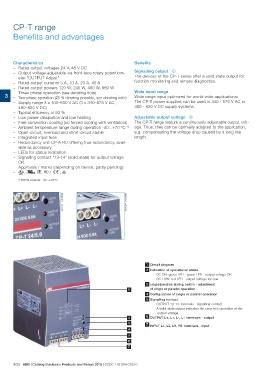
1 Circuit diagram
2 Indication of operational states
DC ON: green LED - green LED - output voltage OK
DC LOW: red LED - output voltage too low
3 single/parallel: sliding switch - adjustment
1 of single or parallel operation
4 Configuration of single or parallel operation
5 Signalling contact
OUTPUT 13-14: terminals - signalling contact
A solid-state output indicates the error-free operation of the
output voltage.
2 OUTPUT L+, L+, L-, L-: terminals - output
3 7 INPUT L1, L2, L3, PE: terminals - input
4
5
7
3/33 ABB | Catalog Electronic Products and Relays 2015 | 2CDC 110 004 C0210